This document describes the Web API interface to WebGeocalc. The API interface provides a way to perform information queries and invoke calculations in the same way the web browser client does. All requests and responses are processed through HTTP/HTTPS transactions. In addition, request URLs use a RESTful structure with JSON payloads and results.
Last updated 09-DEC-2025.
There is an HTML page available on the WebGeoCalc server which serves as an example of how to call the web API: API Example Page (will open in a new window or tab).
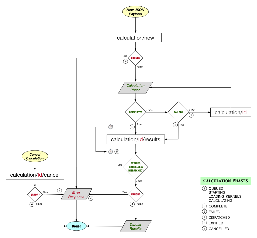
The following diagram provides a flowchart for the client-server communication, linking each of the possible client-side requests to the different phases of a Calculation.
If you are developing a web-based application and planning on integrating WGC API with it, you will need to overcome the Same-Origin Policy enforced by all modern browsers to prevent web pages from making requests to a different domain than the one that served the original web page.
The definition of an origin is simple. Two websites are of the same origin if their scheme (http://, https://, etc.), host (e.g., google.com), and port (e.g., 80, 443, etc.) are the same. For example, these URIs are considered to have the same origin:
https://wgc2.jpl.nasa.gov:8443
https://wgc2.jpl.nasa.gov:8443/webgeocalc/documents/api-info.html
https://wgc2.jpl.nasa.gov:8443/webgeocalc/api/
On the other hand, these URIs are all different origins:
https://www.my-server.com
https://www.my-server.com:8443
https://wgc.api.ext:8443/webgeocalc/api/
As such, direct calls to WGC API from www.my-server.com will
not be allowed by browsers, as they violate the Same-Origin Policy.
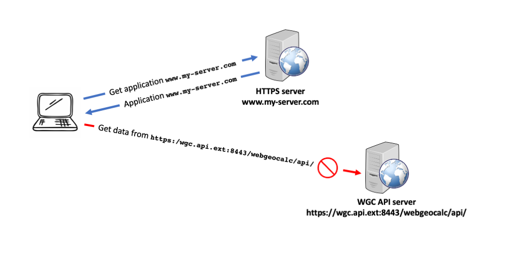
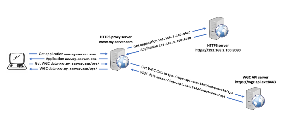
Since WGC API serves multiple users from multiple organizations, and it is not manageable to implement a secure, selective and controlled Cross-Origin Resource Sharing (CORS) policy on our server, WGC API does not support it. But this does not mean that WGC API cannot be integrated with your own web application. The implementation of an HTTP/HTTPS reverse proxy within your organization is an effective solution for handling the Same-Origin Policy problem, helping to bypass this restriction.
The proxy will filter the incoming requests and forward them to the appropriate resource, which could be on the same machine the proxy is running on, a different machine within your organization's internal network, or an external resource, such as WGC API.
Let's say that you are deploying an application on the URL
www.my-server.com
running HTTPS (port 443), and this application integrates WGC API. Instead of performing requests directly to the WGC API server at
https://wgc2.jpl.nasa.gov:8443/webgeocalc/api/
which would be blocked due to the Same-Origin Policy, your application must direct the WGC API requests to an endpoint on the same URL, e.g.
https://www.my-server.com/wgc/
The proxy, which shall be running on
www.my-server.com
port 443, must be configured to forward the requests for /wgc/
to the WGC API server and all other requests to the web server
serving your application. The later could be on the same machine where the
proxy is deployed or, as in our example, on a different machine, e.g.
https://192.168.2.100:8080
A simple HTTP/HTTPS reverse proxy can be set up using Nginx. Let's
assume that we have Nginx installed on the machine where we want to deploy
our server, and that the SSL/TLS certificates for our domain
www.my-server.com are located in
/local/cert/ssl
We will configure Nginx to run an HTTP and an HTTPS server. The HTTP
server, listening on port 80, will redirect all requests to the HTTPS
server. The HTTPS server, running on port 443, will redirect requests
for /wgc/ to the WGC API server
https://wgc2.jpl.nasa.gov:8443/webgeocalc/api/
and all other requests to the local HTTPS server running on
https://192.168.2.100:8080
The Nginx configuration file nginx.conf, which should be
placed in the Nginx conf.d directory, is shown hereafter.
    #
    # HTTPS server.
    #
    # Requests to /wgc/ are redirected to WGC API server, all others
    # to the HTTPS server running on 192.168.2.100, port 8080
    #
    server {
        listen 443 ssl;
        listen [::]:443 ssl;

        server_name www.my-server.com;

        # Define SSL certificates' location
        ssl_certificate /local/cert/ssl/my-server.crt;
        ssl_certificate_key /local/cert/ssl/my-server-key.pem;

        # If URL match with /wgc/ redirect the request
        location /wgc/ {
            proxy_pass https://wgc2.jpl.nasa.gov:8443/webgeocalc/api/;

            proxy_set_header Host $host;
            proxy_set_header X-Real-IP $remote_addr;
        }

        # In any other case send the request to the local server
        location / {
            proxy_pass https://192.168.2.100:8080/;

            proxy_set_header Host $host;
            proxy_set_header X-Real-IP $remote_addr;
        }
    }

    #
    # HTTP server.
    #
    # http requests are redirected to https, within the same machine.
    #
    server {

        listen 80;
        listen [::]:80;

        server_name www.my-server.com;
        return 302 https://$server_name$request_uri;
    }
If we have Docker on the machine where we want to deploy the HTTP/HTTPS
proxy, the SSL/TLS certificates for our domain
www.my‑server.com are located in
/home/user/proxy/cert/ssl/
and the Nginx configuration file shown in the previous section in
/home/user/proxy/config/
we could use the following Dockerfile to create an image for deploying our reverse proxy, which will be listening on ports 80 and 443 for http and https requests.
   # Filename: Dockerfile
   #
   # Use an official Docker Nginx image, running on alpine OS.
   #
   FROM nginx:stable-alpine

   #
   # The official Nginx image has the Nginx default access and error logs
   # linked to /dev/stdout and /dev/stderr. The following command, makes
   # them files, which can be access through a shared folder. If you want
   # the logs to be reported on the terminal, comment out the following
   # lines.
   #
   RUN unlink /var/log/nginx/access.log \
    && unlink /var/log/nginx/error.log  \
    && touch  /var/log/nginx/access.log \
    && touch  /var/log/nginx/error.log

   #
   # Copy the required files in the appropriate locations within the image.
   #
   COPY config/nginx.conf /etc/nginx/conf.d/default.conf
   COPY --chmod=600 ssl/*.* /etc/nginx/ssl/
The previous file shall be named Dockerfile and be placed in
/home/user/proxy/
In order to deploy the container with the proxy, first we need to build the image. From the directory where we have the Dockerfile file, run
docker build -t https-proxy:1.0 -f Dockerfile .
This command creates an image called https-proxy. Once we
have built the image, we can deploy the Docker container by running
   docker run -d -p 80:80 -p 443:443                     \
              -v /home/user/proxy/logs:/var/log/nginx    \
              --name NginxProxy https-proxy:1.0
By doing this, we have our HTTP/HTTPS proxy listening on ports 80 and 443 ready for operations. The container runs on the background, the access and error logs are placed in
/home/user/proxy/logs
and no information is reported on the terminal. If we want the Nginx logs
to be printed on the terminal, we need to comment out the RUN
statement in the Dockerfile, rebuild the image, and run the
previous command without the -d and -v
options:
docker run -p 80:80 -p 443:443 --name NginxProxy https-proxy:1.0
All URLs listed here are relative to the context root for the WebGeocalc application. The context root will vary based on the server configuration. As of this writing, the context root for the API-enabled WebGeocalc installation at NAIF is https://wgc2.jpl.nasa.gov:8443/webgeocalc/api/.
For example, the relative URL for the request to list kernel sets is api/kernel-sets. To invoke this request at the main NAIF site, the complete URL would be https://wgc2.jpl.nasa.gov:8443/webgeocalc/api/kernel-sets.
This section describes those API requests for getting information about the version of the WebGeocalc API currently deployed on the server.
Get a short description, a link to the main documentation page (this page), the version number and the build identifier of the WebGeocalc Programmatic Interface (API).
| URL parameters | None |
|---|---|
| Request payload | None |
| Response format | JSON with the WGC API information. |
| Example request URL | https://wgc2.jpl.nasa.gov:8443/webgeocalc/api/ |
|---|---|
| Example response |
{
   "title": "WebGeocalc by NAIF",
   "description": "WGC2 -- a WebGeocalc Server with enabled API at NAIF, JPL",
   "documentation": "https://wgc2.jpl.nasa.gov:8443/webgeocalc/documents/api-info.html",
   "contact": "Boris Semenov <boris.semenov@jpl.nasa.gov>",
   "version": "2.2.0",
   "build_id": "4599 N66 19-DEC-2019"
}
|
This section describes those API requests for getting information about the available kernel sets on the WebGeocalc server.
Get list of kernel sets available on the server.
| URL parameters | None |
|---|---|
| Request payload | None |
| Response format | JSON with list of kernel set objects |
| Example request URL | https://wgc2.jpl.nasa.gov:8443/webgeocalc/api/kernel-sets |
|---|---|
| Example response |
{
  "status": "OK",
  "message": "The request was successful.",
  "resultType": "KernelSetDetails",
  "items":[
    {
      "caption": "Solar System Kernels",
      "sclkId": "0",
      "description": "Generic kernels for planets, satellites, and some asteroids covering from 1950-01-01 to 2050-01-01.",
      "kernelSetId": "1",
      "missionId": "gen"
    },
    ...
  ]
}
|
Get list of bodies available in a kernel set.
| URL parameters | kernelSetId, an integer |
|---|---|
| Request payload | None |
| Response format | JSON with list of body objects |
| Example request URL | https://wgc2.jpl.nasa.gov:8443/webgeocalc/api/kernel-set/5/bodies |
|---|---|
| Example response |
{
  "status": "OK",
  "message": "The request was successful.",
  "resultType": "BodyData",
  "items": [
    {
      "id": -82,
      "name": "CASSINI"
    },
    ...
  ]
}
|
Get list of frames available in a kernel set.
| URL parameters | kernelSetId, an integer |
|---|---|
| Request payload | None |
| Response format | JSON with list of frame objects |
| Example request URL | https://wgc2.jpl.nasa.gov:8443/webgeocalc/api/kernel-set/5/frames |
|---|---|
| Example response |
{
  "status": "OK",
  "message": "The request was successful.",
  "resultType": "FrameData",
  "items": [
    {
      "id": -82905,
      "name": "CASSINI_KSO",
      "centerBodyID": 699,
      "frameClass": 5
    },
    ...
  ]
}
|
Get list of instruments available in a kernel set.
| URL parameters | kernelSetId, an integer |
|---|---|
| Request payload | None |
| Response format | JSON with list of instrument objects |
| Example request URL | https://wgc2.jpl.nasa.gov:8443/webgeocalc/api/kernel-set/5/instruments |
|---|---|
| Example response |
{
  "status": "OK",
  "message": "The request was successful.",
  "resultType": "InstrumentData",
  "items": [
    {
      "id": -82898,
      "name": "CASSINI_CIRS_RAD"
    },
    ...
  ]
}
|
This section details the API requests used to invoke calculations and get their status or results.
Starts a new calculation.
| URL parameters | None |
|---|---|
| Request payload | JSON with calculation parameters |
| Response format | JSON with calculation creation status, or with an error, if detected before the response is created. |
The payload JSON object that is sent as POST data needs the following standard parameters.
| Name | Value |
|---|---|
| calculationType | The type of calculation to perform. One of the following:
|
| kernels | The kernels parameter must be an array of kernels
or kernel sets. To specify a kernel set use an object like this:
     {
       "type": "KERNEL_SET",
       "id": "the kernel set ID, an integer"
     }
To specify an individual kernel, use an object like this:
     {
       "type": "KERNEL",
       "path": "the server path to the kernel"
     }
|
| timeSystem | One of the following:
If SPACECRAFT_CLOCK is selected, then sclkId must also be provided. Note that in SPICE, TDT (Terrestrial Dynamical Time) and TT (Terrestrial Time) refer to the same time system. |
| timeFormat | One of the following:
CALENDAR is applicable only when timeSystem is UTC, TDB, TDT, TT or GPS. JULIAN and SECONDS_PAST_J2000 are applicable only when timeSystem is UTC, TDB, TDT or TT. SPACECRAFT_CLOCK_STRING and SPACECRAFT_CLOCK_TICKS are applicable only when timeSystem is SPACECRAFT_CLOCK. SECONDS_PAST_GPS0 and WEEK_TOW are applicable only when timeSystem is GPS. |
| sclkId | The SCLK ID. Only used if timeSystem is SPACECRAFT_CLOCK. |
| times | An array of strings representing the time points that should be used in the calculation. E.g.
     "times": [
       "2000-01-01",
       "2000-01-02"
     ],
Either this parameter or the intervals parameter must be supplied.
|
| intervals | An array of objects with startTime and endTime parameters,
representing the time intervals used for the calculation. E.g.
     "intervals": [
       {
         "startTime": "2000-01-01",
         "endTime": "2000-01-02"
       }
     ],
Either this parameter or the times parameter
must be supplied. If this parameter is used, timeStep must also be supplied.
|
| timeStep | The timeStep parameter used for time series or
geometry finder calculations. This parameter is not used for time
series calculations if the times parameter is supplied.
For time series calculations, timeStep determines how calculation times are selected within the specified intervals. When multiple intervals are provided, the start and stop times of all of them (after merging any overlapping ones) are always included in the output. If an interval is shorter than the sampling step, only its start and stop times are included. If an interval consists of a single time point, only that time is included. When a single interval is provided, the stop time will be included in the output only if it coincides with one of the computed samples. For geometry finder calculations, timeStep determines the step size to be used in the search. |
| timeStepUnits | One of the following:
When sampling by seconds, minutes, hours, days, or SCLK duration provided as a duration string or ticks, the last time before the interval's stop time will be between 0.5 and 1.5 sampling steps before the interval's stop time. When a specific number of samples is requested, the sampling step is calculated by dividing the total duration of all intervals by the number of requested samples minus the number of intervals. In general, when multiple intervals are specified, records in the output table will not be equally spaced. |
| samplingTimeSystem | The time system used to compute the sampling step. One of the
following:
|
All the calculation types starting with GF_ require these additional parameters:
| Name | Description |
|---|---|
| outputDurationUnits | The units for the duration
column of each interval in the result window. One of:
|
| shouldComplementWindow | A flag indicating whether to
complement the result window against the original search window
before returning the result. One of:
|
| intervalAdjustment | An indication whether to adjust
the intervals by expansion or contraction. If specified, both
intervalAdjustmentAmount and
intervalAdjustmentAmountUnits must be specified. One of:
|
| intervalAdjustmentAmount | The amount to adjust each interval endpoint. |
| intervalAdjustmentUnits | The time units for
the interval adjustment amount. One of:
|
| intervalFiltering | Whether to filter out intervals
smaller than a threshold. If specified, both
intervalFilteringThreshold and
intervalFilteringThresholdUnits must be specified. One of:
|
| intervalFilteringThreshold | The duration threshold value. All intervals shorter than this value will be removed from the result window. |
| intervalFilteringThresholdUnits | The time unit for
the interval filtering threshold. One of:
|
In addition, all scalar GF calculations (GF_COORDINATE_SEARCH, GF_ANGULAR_SEPARATION_SEARCH, GF_DISTANCE_SEARCH, GF_ILLUMINATION_ANGLES_SEARCH, GF_PHASE_ANGLE_SEARCH, GF_RANGE_RATE_SEARCH, GF_SUB_POINT_SEARCH, and GF_SURFACE_INTERCEPT_POINT_SEARCH) require the user to specify a condition to test during the search. This condition is a Javascript object with several parameters.
| Name | Description | |
|---|---|---|
| coordinateSystem | The name of the coordinate system
in which to evaluate the coordinate. Only required for
GF_COORDINATE_SEARCH, GF_SUB_POINT_SEARCH, and
GF_SURFACE_INTERCEPT_POINT_SEARCH. One of:
| |
| coordinate | The name of the SPICE coordinate to search on.
Only required for GF_COORDINATE_SEARCH, GF_SUB_POINT_SEARCH, and GF_SURFACE_INTERCEPT_POINT_SEARCH. One of:
This coordinate must be appropriate for
the coordinateSystem. See the SPICE API call
| |
| azccwFlag | Flag indicating how azimuth is measured. If azccwFlag is true, azimuth increases in the counterclockwise direction; otherwise it increases in the clockwise direction. Required only when coordinate is AZIMUTH. | |
| elplszFlag | Flag indicating how elevation is measured. If elplszFlag is true, elevation increases from the XY plane toward +Z; otherwise toward -Z. Required only when coordinate is ELEVATION. | |
| angleType | The name of the SPICE angle to search on.
Only required for GF_ILLUMINATION_ANGLES_SEARCH. One of:
| |
| relationalCondition | The relationship for the test. One of:
gfpos().
Note that for RANGE searches, the referenceValue and upperLimit values do not need to be in increasing order. If these values are in decreasing order, in the case of coordinate being LONGITUDE, RIGHT ASCENSION or AZIMUTH, the search will be performed across the boundary. For all other coordinates, the referenceValue and upperLimit values will be "swapped." | |
| referenceValue | The value to compare against, or the lower value of a range. Only needed if relationalCondition is not ABSMAX, ABSMIN, LOCMAX, or LOCMIN. | |
| upperLimit | The upper limit of a range. Only needed if relationalCondition is RANGE. | |
| adjustmentValue | The adjustment value to apply for
ABSMIN and ABSMAX searches. Required if relationalCondition
is ABSMIN or ABSMAX.
The units associated with the adjustmentValue are either degrees, km or km/s, depending on the selected search constraint, coordinate or angleType. See the documentation for |
For example, here is a sample condition for GF_COORDINATE_SEARCH, which should serve as prototype for all cases where coordinateSystem is required:
"condition": {
  "coordinateSystem": "RA/DEC",
  "coordinate": "DECLINATION",
  "relationalCondition": "<",
  "referenceValue": -5
}
Here is a sample condition for GF_ILLUMINATION_ANGLES_SEARCH:
"condition": {
  "angleType": "EMISSION",
  "relationalCondition": "ABSMAX",
  "adjustmentValue": 0.0001
}
For other searches, the coordinateSystem and coordinate are implied. For example, here is a condition for GF_DISTANCE_SEARCH:
"condition": {
  "relationalCondition": "ABSMIN",
  "adjustmentValue": 1000
}
Direction vectors for ANGULAR_SEPARATION and POINTING_DIRECTION are specified as JSON dictionaries, using the following parameters:
| Name | Description |
|---|---|
| directionType | Method used to specify a direction. Directions could be specified as
the position of an object as seen from the observer, as the velocity
vector of an object as seen from the observer in a given reference
frame, or by providing a vector in a given reference frame. One of:
Velocity depends on the reference frame in which it is expressed. Given a time-dependent frame transformation R(t) between "input" and "output" reference frames, and position and velocity vectors expressed in the input frame, the velocity transformation between the frames can be expressed asVel_out(t) = d(R(t))/dt * Pos_in(t) + R(t) * Vel_in(t)In some cases, velocity is used simply as a direction vector; the rate of change of position in the output frame is not relevant. In these cases, the above transformation reduces to Vel_out(t) = R(t) * Vel_in(t) This is the transformation used when velocity is treated as a direction vector. Examples:
Depending on the desired directionType, different parameters are required. The following sections provide the list of additional parameters per directionType value. |
Additional Parameters for Direction Vector of type POSITION
| Name | Description |
|---|---|
| target | The target body name or ID |
| shape | The shape to use for the target body, only required
for ANGULAR_SEPARATION
computations. One of:
|
| observer | The observing body name or ID |
| aberrationCorrection | The SPICE aberration correction
string. One of:
|
| antiVectorFlag | true if the anti-vector shall be used for the direction, and false otherwise. Required when the target shape is POINT. If provided when the target shape is SPHERE, it must be set to false, i.e. using anti-vector direction is not supported for target bodies modeled as spheres. |
For example, here is a sample POSITION type direction1 specification for ANGULAR_SEPARATION computation:
"direction1": {
  "directionType": "POSITION",
  "target": "MARS",
  "shape": "POINT",
  "observer": "EARTH",
  "aberrationCorrection": "LT+S",
  "antiVectorFlag": false
}
Here is a sample POSITION type direction specification for POINTING_DIRECTION computation:
"direction": {
  "directionType": "POSITION",
  "target": "MARS",
  "observer": "EARTH",
  "aberrationCorrection": "LT+S",
  "antiVectorFlag": false
}
Additional Parameters for Direction Vector of type VELOCITY
| Name | Description |
|---|---|
| target | The target body name or ID |
| referenceFrame | The reference frame name |
| observer | The observing body name or ID |
| aberrationCorrection | The SPICE aberration correction
string. One of:
|
| antiVectorFlag | true if the anti-vector shall be used for the direction, and false otherwise. |
For example, here is a sample VELOCITY type direction1 specification for ANGULAR_SEPARATION computation:
"direction1": {
  "directionType": "VELOCITY",
  "target": "MARS",
  "referenceFrame": "ITRF93",
  "observer": "EARTH",
  "aberrationCorrection": "XCN+S",
  "antiVectorFlag": true
}
Here is a sample VELOCITY type direction specification for POINTING_DIRECTION computation:
"direction": {
  "directionType": "VELOCITY",
  "target": "MARS",
  "referenceFrame": "ITRF93",
  "observer": "EARTH",
  "aberrationCorrection": "XCN+S",
  "antiVectorFlag": true
}
Additional Parameters for Direction Vector of type VECTOR
| Name | Description |
|---|---|
| directionVectorType | Type of vector to be used as the ray direction: the instrument
boresight vector, an axis of the specified reference frame, a vector
in the reference frame of the specified instrument, a vector in the
specified reference frame, or the instrument field-of-view boundary
vectors (only for POINTING_DIRECTION
computations). One of:
|
| directionInstrument | The instrument name or ID. Required only if directionVectorType is INSTRUMENT_BORESIGHT, VECTOR_IN_INSTRUMENT_FOV or INSTRUMENT_FOV_BOUNDARY_VECTORS. |
| directionFrame | The vector's reference frame name. Required only if directionVectorType is REFERENCE_FRAME_AXIS or VECTOR_IN_REFERENCE_FRAME. |
| directionFrameAxis | The direction vector frame axis. Required only if
directionVectorType is REFERENCE_FRAME_AXIS. One of:
|
| directionVectorX | The X direction vector coordinate. If directionVectorType is VECTOR_IN_INSTRUMENT_FOV or VECTOR_IN_REFERENCE_FRAME, then either all three of directionVectorX, directionVectorY, and directionVectorZ must be provided, or both directionVectorRA and directionVectorDec, or both directionVectorAz and directionVectorEl. |
| directionVectorY | The Y direction vector coordinate. |
| directionVectorZ | The Z direction vector coordinate. |
| directionVectorRA | The right ascension direction vector coordinate. |
| directionVectorDec | The declination direction vector coordinate. |
| directionVectorAz | The azimuth direction vector coordinate. |
| directionVectorEl | The elevation direction vector coordinate. |
| azccwFlag | Flag indicating how azimuth is measured. If azccwFlag is true, azimuth increases in the counterclockwise direction; otherwise it increases in the clockwise direction. Required only when directionVectorAz and directionVectorEl are used to provide the coordinates of the direction vector. |
| elplszFlag | Flag indicating how elevation is measured. If elplszFlag is true, elevation increases from the XY plane toward +Z; otherwise toward -Z. Required only when directionVectorAz and directionVectorEl are used to provide the coordinates of the direction vector. |
| aberrationCorrection | The SPICE aberration correction
string. Light time correction is applied to the rotation from the vector
frame to J2000, while stellar aberration corrections apply to the vector
direction. One of:
|
| observer | The observing body name or ID. Required if aberrationCorrection is not NONE. |
| antiVectorFlag | true if the anti-vector shall be used for the direction, and false otherwise. |
For example, here is a sample VECTOR type direction1 specification for ANGULAR_SEPARATION computation:
"direction1": {
  "directionType": "VECTOR",
  "observer": "EARTH",
  "directionVectorType": "REFERENCE_FRAME_AXIS",
  "directionFrame": "IAU_EARTH",
  "directionFrameAxis": "X",
  "aberrationCorrection": "S",
  "antiVectorFlag": true
}
Here is a sample VECTOR type direction specification for POINTING_DIRECTION computation:
"direction": {
  "directionType": "VECTOR",
  "observer": "CASSINI",
  "directionVectorType": "INSTRUMENT_FOV_BOUNDARY_VECTORS",
  "directionInstrument": "CASSINI_ISS_NAC",
  "aberrationCorrection": "CN",
  "antiVectorFlag": false
}
The calculations ILLUMINATION_ANGLES and GF_ILLUMINATION_ANGLES_SEARCH require the following parameters in order to specify the target body surface point on which the computations will be conducted:
| Name | Description |
|---|---|
| target | The target body name or ID |
| shape1 | The shape to use to model the surface of the target body. One of:
|
| targetFrame | The body-fixed reference frame name, centered at target. |
| offSurfaceFlag | Flag indicating whether the location is given as an off-surface
point (true) or not (false). Surface points on a target body's
reference ellipsoid normally should be specified by two angular coordinates, for
example planetocentric longitude and latitude. These coordinates identify a unique
point on the ellipsoid, which then can be converted to Cartesian coordinates by WGC.
If this flag is set to true, you can specify a point off the reference ellipsoid. The direction of the outward normal vector calculated by WGC at this point won't be exactly parallel to the outward normal direction at the nearest point on the reference ellipsoid to the specified input point. The angular offset between the directions typically is small for points not far from the reference ellipsoid. Some examples are:
|
| coordinateRepresentation | One of:
|
| latitude | The latitude coordinate of the surface point, in degrees. Required only when coordinateRepresentation is LATITUDINAL, PLANETODETIC or PLANETOGRAPHIC. |
| longitude | The longitude coordinate of the surface point, in degrees. Required only when coordinateRepresentation is LATITUDINAL, PLANETODETIC, PLANETOGRAPHIC, SPHERICAL or CYLINDRICAL. |
| colatitude | The colatitude coordinate of the surface point, in degrees. Required only when coordinateRepresentation is SPHERICAL. |
| radius | The radius coordinate at the surface point location, in km. Required only when coordinateRepresentation is LATITUDINAL, CYLINDRICAL or SPHERICAL and offSurfaceFlag is set to true. |
| altitude | The altitude coordinate of the surface point, in km. Required only when coordinateRepresentation is PLANETODETIC, or PLANETOGRAPHIC and offSurfaceFlag is set to true. |
| x | The X coordinate of the surface point, in km. Required only when coordinateRepresentation is RECTANGULAR. |
| y | The Y coordinate of the surface point, in km. Required only when coordinateRepresentation is RECTANGULAR. |
| z | The Z coordinate of the surface point, in km. Required only when coordinateRepresentation is RECTANGULAR or CYLINDRICAL. |
Note that in the case of Surface Point specification, the parameters are NOT grouped in a Javascript object.
For example, here is a sample of the specification of an on-surface point on a target modeled using a DSK:
  "target": "ENCELADUS",
  "shape1": "DSK",
  "targetFrame": "IAU_ENCELADUS",
  "observer": "CASSINI",
  "coordinateRepresentation": "LATITUDINAL",
  "latitude": 0,
  "longitude": 0,
And a sample of the specification of an off-surface point on a target modeled as an ellipsoid:
  "target": "SATURN",
  "shape1": "ELLIPSOID",
  "offSurfaceFlag": true,
  "targetFrame": "IAU_SATURN",
  "coordinateRepresentation": "PLANETODETIC",
  "latitude": 90.0,
  "longitude": 0,
  "altitude": 10.25,
See the details for each calculation type and the parameter reference for information about other parameters:
| Example Request URL | https://wgc2.jpl.nasa.gov:8443/webgeocalc/api/calculation/new |
|---|---|
| Example Post Data |
{
  "calculationType": "STATE_VECTOR",
  "kernels": [
    {
      "type": "KERNEL_SET",
      "id": 1
    }
  ],
  "timeSystem": "UTC",
  "timeFormat": "CALENDAR",
  "intervals": [
    {
      "startTime": "2000-01-01",
      "endTime": "2000-01-02"
    }
  ],
  "timeStep": 30,
  "timeStepUnits": "MINUTES",
  "targetType": "OBJECT",
  "target": "SUN",
  "observerType": "OBJECT",
  "observer": "EARTH",
  "referenceFrame": "J2000",
  "aberrationCorrection": "NONE",
  "stateRepresentation": "RA_DEC"
}
|
| Example Response |
{
  "status": "OK",
  "message": "The request was successful.",
  "calculationId": "0788aba2-d4e5-4028-9ef1-4867ad5385e0",
  "result": {
    "phase": "COMPLETE",
    "expiresIn": 54
  }
}
|
Gets the status of a calculation.
| URL parameters | calculationId, a string |
|---|---|
| Request payload | None |
| Response format | JSON with calculation status, or with an error, if the provided calculation identifier calculationId does not correspond to any previously requested calculation, or if the calculation has been removed from the server. |
| Example request URL | https://wgc2.jpl.nasa.gov:8443/webgeocalc/api/calculation/0788aba2-d4e5-4028-9ef1-4867ad5385e0 |
|---|---|
| Example response |
{
  "status": "OK",
  "message": "The request was successful.",
  "calculationId": "0788aba2-d4e5-4028-9ef1-4867ad5385e0",
  "result": {
    "phase": "COMPLETE",
    "expiresIn": 54
  }
}
|
Gets the results of a calculation, should it be successfully COMPLETE. If the calculation status phase is FAILED, it returns an error response providing relevant information about the error. Upon serving this request, the results (or error details) are removed from the server, and calculation status phase is set to DISPATCHED.
Requesting results during any other calculation phase will produce an error.
| URL parameters | calculationId, a string |
|---|---|
| Request payload | None |
| Response format | JSON with calculation results, or with an error, should the calculation FAILED after the response to the request for a new calculation was served, or if the provided calculation identifier calculationId does not correspond to any previously requested calculation, or if the calculation has been removed from the server. |
| Example request URL | https://wgc2.jpl.nasa.gov:8443/webgeocalc/api/calculation/0788aba2-d4e5-4028-9ef1-4867ad5385e0/results |
|---|---|
| Example response |
{
  "status": "OK",
  "message": "The request was successful.",
  "calculationId": "0788aba2-d4e5-4028-9ef1-4867ad5385e0",
  "columns": [
    {
      "name": "UTC calendar date",
      "type": "DATE",
      "units": "",
      "outputID": "DATE"
    },
    {
      "name": "Right Ascension (deg)",
      "type": "NUMBER",
      "units": "deg",
      "outputID": "RIGHT_ASCENSION"
    },
    ...
    {
      "name": "Light Time (s)",
      "type": "NUMBER",
      "units": "s",
      "outputID": "LIGHT_TIME"
    }
  ],
  "rows": [
    [
      "2000-01-01 00:00:00.000000 UTC",
      280.73666816,
      -23.07197828,
      147104359.15044397,
      0.0000127884715,
      8.74255781e-7,
      -0.01659221,
      30.29084386,
      "2000-01-01 00:00:00.000000 UTC",
      490.6873246
    ],
    ...
    [
      "2000-01-02 00:00:00.000000 UTC",
      281.84100169,
      -22.99260787,
      147103258.34983575,
      0.0000127745341,
      9.62949471e-7,
      -0.00894244,
      30.29324424,
      "2000-01-02 00:00:00.000000 UTC",
      490.68365272
    ]
  ]
}
|
Cancels a previously requested calculation, should this not be completed, or its results.
Calculations that have been already DISPATCHED, previously CANCELLED or that have EXPIRED cannot be canceled, and requesting it will produce an error.
| URL parameters | calculationId, a string |
|---|---|
| Request payload | None |
| Response format | JSON with calculation status, or with an error, if the provided calculation identifier calculationId does not correspond to any previously requested calculation, or if this calculation has been removed from the server. |
| Example request URL | https://wgc2.jpl.nasa.gov:8443/webgeocalc/api/calculation/0788aba2-d4e5-4028-9ef1-4867ad5385e0/cancel |
|---|---|
| Example response |
{
  "status": "OK",
  "message": "The request was successful.",
  "calculationId": "0788aba2-d4e5-4028-9ef1-4867ad5385e0",
  "result": {
    "phase": "CANCELLED"
  }
}
|
This section describes the available response types and their parameters.
The Calculation Status Response are returned for successful calculation/new, calculation/id, and calculation/id/cancel requests.
The Calculation Results Response are returned as response to calculation/id/results requests only for successfully completed, non-expired calculations.
The Error Response can be returned for any requests.
All responses have at least three parameters:
| Name | Description |
|---|---|
| status | The status of the request. Either OK or ERROR |
| message | A short message describing the status of the request. |
| calculationId | A string representing the calculation task identifier generated by the calculation service. |
The calculation status response is received upon successful processing of a new request for calculation, a request for the status of an existing calculation task, or its successful cancellation. Besides the Common Parameters, the response includes the result JSON object, which contains the following parameters:
| Name | Description |
|---|---|
| phase | The status (phase) of the calculation. One of:
|
| position | The current position of the calculation request within the calculation service queue. This parameter is only provided if the phase is QUEUED. |
| expiresIn | Number of seconds, from the time the status information has been generated, until the results produced by the calculation request are purged from the calculation service, i.e. the results associated to the given calculationId will be removed from the server, and therefore no longer available, after expiresIn seconds. This parameter is only provided if the phase is COMPLETE. |
| QUEUED phase | {
"status": "OK",
"message": "The request was successful.",
"calculationId": "02c0b4c5-8a8a-4fdb-8a07-b446c6e6722a",
"result": {
"phase": "QUEUED",
"position": 6
}
} |
|---|---|
| STARTING phase | {
"status": "OK",
"message": "The request was successful.",
"calculationId": "9192ebe1-37ef-41dc-81d2-03bb0e5ae956",
"result": {
"phase": "STARTING"
}
} |
| LOADING_KERNELS phase | {
"status": "OK",
"message": "The request was successful.",
"calculationId": "9192ebe1-37ef-41dc-81d2-03bb0e5ae956",
"result": {
"phase": "LOADING_KERNELS"
}
} |
| CALCULATING phase | {
"status": "OK",
"message": "The request was successful.",
"calculationId": "9192ebe1-37ef-41dc-81d2-03bb0e5ae956",
"result": {
"phase": "CALCULATING"
}
} |
| COMPLETE phase | {
"status": "OK",
"message": "The request was successful.",
"calculationId": "26d33ccc-a49c-41e5-a733-9c24b04b9fb9",
"result": {
"phase": "COMPLETE",
"expiresIn": 54
}
} |
| FAILED phase | {
"status": "OK",
"message": "The request was successful.",
"calculationId": "9192ebe1-37ef-41dc-81d2-03bb0e5ae956",
"result": {
"phase": "FAILED"
}
} |
| CANCELLED phase | {
"status": "OK",
"message": "The request was successful.",
"calculationId": "9192ebe1-37ef-41dc-81d2-03bb0e5ae956",
"result": {
"phase": "CANCELLED"
}
} |
| DISPATCHED phase | {
"status": "OK",
"message": "The request was successful.",
"calculationId": "9192ebe1-37ef-41dc-81d2-03bb0e5ae956",
"result": {
"phase": "DISPATCHED"
}
} |
| EXPIRED phase | {
"status": "OK",
"message": "The request was successful.",
"calculationId": "9192ebe1-37ef-41dc-81d2-03bb0e5ae956",
"result": {
"phase": "EXPIRED"
}
} |
The calculation results response is received upon successful processing of a request for the results (calculation/id/results request) of a COMPLETE calculation task.
Note that the results for a given calculation, with task identifier calculationId, will be available on the server for a limited time. The remaining seconds until the results are discarded can be obtained by requesting the status of the calculation once it is completed. The server provides this information in the expiresIn parameter of the Calculation Status Response.
Upon retrieval of the calculation results, they are removed from the server, and are no longer available. The phase of the calculation is then set to DISPATCHED.
Besides the Common Parameters, the response includes the columns and rows JSON objects, representing a table.
The columns JSON object contains an array of JSON objects, each of them containing the following parameters:
| Name | Description |
|---|---|
| name | A string providing the name of the table's column, giving a short description of the values provided within that column, e.g. "UTC calendar date". |
| type | Column's data type. One of:
|
| units | Units in which the column's value is given, or an empty string if the concept of units does not apply to the values in that column. |
| outputID | Unique column identifier. This identifier is unique across all results generated by WGC. |
The rows JSON object contains an array of arrays of values, each of them containing as many values as columns have been described within the columns object.
If the provided results correspond to a 7x3 table, the rows object will have 7 arrays of 3 strings each, and the columns object will have 3 objects describing each of the three columns.
| Example Results | {
"status": "OK",
"message": "The request was successful.",
"calculationId": "8fb3afe9-3d77-4c30-9c00-80be816ce942",
"columns": [
{
"name": "UTC calendar date",
"type": "DATE",
"units": "",
"outputID": "DATE"
},
{
"name": "UTC Julian date",
"type": "NUMBER",
"units": "",
"outputID": "DATE2"
}
],
"rows": [
[
"2000-01-01 00:00:00.000000 UTC",
"2451544.500000000 JD UTC"
],
[
"2000-01-02 00:00:00.000000 UTC",
"2451545.500000000 JD UTC"
],
[
"2000-02-01 00:00:00.000000 UTC",
"2451575.500000000 JD UTC"
],
[
"2000-02-02 00:00:00.000000 UTC",
"2451576.500000000 JD UTC"
]
]
} |
|---|
The error response is received upon detection of an error, on the server side, either during the processing of the request, in the calculation task or in the generation of the results. Should a Calculation task Identifier exist at the time the error is detected, the Calculation Phase is set to FAILED, otherwise the request is completely discarded and the response parameter calculationId is set to null before returning the error response.
In the event that the error is detected in a new calculation request before the request is processed, the server will return an error response instead of the expected Calculation Status Response. Should the error be detected afterward, the client shall use the calculation/id/results request in order to retrieve the error description.
Upon retrieval of the error response, the error details are removed from the server, and are no longer available. The phase of the calculation is then set to DISPATCHED.
Besides the Common Parameters, the error response includes the error JSON object, which contains the following parameters:
| Name | Description |
|---|---|
| shortDescription | A string providing a short description of the reason for the error. |
Note that in all error response objects, the status parameter is set to ERROR.
| Excessive load on the server, response to a calculation/new request. | {
"status": "ERROR",
"message": "The request has failed.",
"calculationId": null,
"error": {
"shortDescription": "The server is currently experiencing excessive load."
}
} |
|---|---|
| Missing required JSON parameter in a calculation/new Calculation Request. | {
"status": "ERROR",
"message": "The request has failed.",
"calculationId": "e145c522-dbb0-49f2-8624-eddc423c3a25",
"error": {
"shortDescription": "No input value found with name 'sclkId'"
}
} |
| SPICE related error, from either a calculation/new or a calculation/id/results request. | {
"status": "ERROR",
"message": "The request has failed.",
"calculationId": "f9c9373b-c455-417c-9b62-f960a5bc5d93",
"error": {
"shortDescription": "CSPICE_N0066: CSPICE.scencd: SPICE(KERNELVARNOTFOUND): [scencd_c --> SCENCD --> SCTIKS --> SCTYPE --> SCLI01] SCLK_DATA_TYPE_825 not found. Did you load the SCLK kernel?"
}
} |
| Attempt to retrieve Results, using a calculation/id/results request, before COMPLETE. | {
"status": "ERROR",
"message": "The request has failed.",
"calculationId": "85a5d697-0163-4525-8056-30fcf0a25620",
"error": {
"shortDescription": "Application should not retrieve results before calculation is finished."
}
} |
| Attempt to retrieve EXPIRED Results, using a calculation/id/results request. | {
"status": "ERROR",
"message": "The request has failed.",
"calculationId": "8d44762c-2ae9-4d6f-bb00-ba39b41b009c",
"error": {
"shortDescription": "The requested results have already expired."
}
} |
| Unknown calculationId error response to a calculation/id, calculation/id/results or calculation/id/cancel request. | {
"status": "ERROR",
"message": "The request has failed.",
"calculationId": "f9c9373-c455-417c-9b62-f960a5bc5d93",
"error": {
"shortDescription": "The provided Calculation ID does not correspond to any requested calculation."
}
} |
This section describes the available calculation types, specified using the parameter calculationType, and the parameters expected by each calculation.
Calculates the state (position and velocity) of a target with respect to an observer, in a specified reference frame. The position and orientation of the target may be corrected for light time and stellar aberration.
Both the target and the observer can be either ephemeris objects or locations 1) having a constant position in a specified reference frame relative to its center of motion (an ephemeris object) or 2) moving at a constant Cartesian velocity from an initial position at a specified epoch, both expressed in a given reference frame, relative to its center of motion (an ephemeris object). Specifying both target and observer as locations is not allowed.
When either the target or the observer is given as a location, the output reference frame orientation, relative to the J2000 frame, will be evaluated at a location given by the frame's locus, which will specify the epoch at which its orientation is computed.
When the observer is given as a fixed location, the output reference frame could be a SPICE reference frame or a local topocentric frame based on the surface normal and direction to the north at the location.
Additional parameters required:
| Name | Description |
|---|---|
| targetType | The type of specification used to define the location of the target. One of:
Note that if targetType is either FIXED_POINT or CONSTANT_VELOCITY_POINT then observerType MUST be OBJECT, i.e. specifying both Target and Observer as locations is not allowed. Note that targetType is optional. If not provided, it is assumed to be OBJECT. |
| target | The target body name or ID, only applicable when targetType is OBJECT. |
| targetLocation | Javascript object providing the specification for the target location, only applicable when targetType is either FIXED_POINT or CONSTANT_VELOCITY_POINT. This dictionary shall comply to the specification provided in Additional Parameters for Locations as Points. |
| observerType | The type of specification used to define the location of the observer.
One of:
Note that if observerType is either FIXED_POINT or CONSTANT_VELOCITY_POINT then targetType MUST be OBJECT, i.e. specifying both Target and Observer as locations is not allowed. Note that observerType is optional. If not provided, it is assumed to be OBJECT. |
| observer | The observing body name or ID, only applicable when observerType is OBJECT. |
| observerLocation | Javascript object providing the specification for the observer location, only applicable when observerType is either FIXED_POINT or CONSTANT_VELOCITY_POINT. This dictionary shall comply to the specification provided in Additional Parameters for Locations as Points. |
| frameType | Defines how the output reference frame is specified. One of:
Note that frameType can only be used when observerType is FIXED_POINT. In this case, frameType is optional. If not provided, it is assumed to be SPICE_FRAME. The local topocentric reference frame is generally defined as follows:
|
| referenceFrame | The reference frame name. Required except when observerType is FIXED_POINT and frameType is TOPOCENTRIC_AT_POINT. |
| frameLocus | The output reference frame evaluation locus; i.e. the location associated
with the epoch at which the evaluation of the output frame's orientation, relative to the J2000 frame,
will be performed. One of:
Use OBSERVER to evaluate the output reference frame at the observer's epoch. Normally the locus OBSERVER should be selected when the output reference frame is centered at the observer. Use TARGET to evaluate the output reference frame at the target epoch. Normally the locus TARGET should be selected when output reference frame is centered at the target object. Use CENTER to evaluate the output reference frame at the epoch associated with its center. The locus CENTER should be selected when the user intends to obtain results compatible with those produced by a state vector computation between two objects, i.e. between a targetType OBJECT and an observerType OBJECT. When the output reference frame is inertial, all choices of frameLocus yield the same results. frameLocus is only applicable when either targetType or observerType is FIXED_POINT or CONSTANT_VELOCITY_POINT, except when observerType is FIXED_POINT and frameType is TOPOCENTRIC_AT_POINT. |
| computationMethod | Defines the computation method to be used to obtain the surface
normal vector that defines the local zenith of the local topocentric reference frame. One of:
|
| aberrationCorrection | The SPICE aberration correction
string. One of:
|
| stateRepresentation | One of:
|
| azccwFlag | Flag indicating how azimuth is measured. If azccwFlag is true, azimuth increases in the counterclockwise direction; otherwise it increases in the clockwise direction. Required only when stateRepresentation is set to AZ_EL. |
| elplszFlag | Flag indicating how elevation is measured. If elplszFlag is true, elevation increases from the XY plane toward +Z; otherwise toward -Z. Required only when stateRepresentation is set to AZ_EL. |
Additional Parameters for specification of locations as points:
Target or observer locations, when defined as points (i.e. when targetType or observerType are either FIXED_POINT or CONSTANT_VELOCITY_POINT), are specified as JSON dictionaries, using the following parameters:
| Name | Description |
|---|---|
| centerBody | the name of the location's center of motion. The ephemeris of centerBody is provided by loaded SPK files. |
| referenceFrame | name of a reference frame, whether built in or defined in loaded kernels.
This reference frame is used to specify the location's coordinates relative to its "center of motion." If coordinateRepresentation (used to specify the location's position) is set to PLANETODETIC or PLANETOGRAPHIC coordinates, this frame shall be non-inertial and its center MUST be the same as the center provided in centerBody. |
| coordinateRepresentation | Coordinate system used to specify the location's position coordinates. One of:
|
| azccwFlag | Flag indicating how azimuth is measured. If azccwFlag is true, azimuth increases in the counterclockwise direction; otherwise it increases in the clockwise direction. Required only when coordinateRepresentation is set to AZ_EL. |
| elplszFlag | Flag indicating how elevation is measured. If elplszFlag is true, elevation increases from the XY plane toward +Z; otherwise toward -Z. Required only when coordinateRepresentation is set to AZ_EL. |
| x | The X coordinate, in km, applicable only when coordinateRepresentation is RECTANGULAR. |
| y | The Y coordinate, in km, applicable only when coordinateRepresentation is RECTANGULAR. |
| z | The Z coordinate, in km, applicable only when coordinateRepresentation is RECTANGULAR or CYLINDRICAL. |
| rightAscension | The right ascension of the location, in degrees, applicable only when coordinateRepresentation is RA_DEC. |
| declination | The declination of the location, in degrees, applicable only when coordinateRepresentation is RA_DEC. |
| range | The range to the location, in km, applicable only when coordinateRepresentation is RA_DEC or AZ_EL. |
| longitude | The longitude of the location, in degrees, applicable only when coordinateRepresentation is LATITUDINAL, PLANETODETIC, PLANETOGRAPHIC, CYLINDRICAL or SPHERICAL. |
| latitude | The latitude of the location, in degrees, applicable only when coordinateRepresentation is LATITUDINAL, PLANETODETIC, or PLANETOGRAPHIC. |
| radius | The radius at the location, in km, applicable only when coordinateRepresentation is LATITUDINAL, CYLINDRICAL or SPHERICAL. |
| altitude | The altitude of the location, in km, applicable only when coordinateRepresentation is PLANETODETIC or PLANETOGRAPHIC. |
| colatitude | The colatitude of the location, in degrees, applicable only when coordinateRepresentation is SPHERICAL. |
| azimuth | The azimuth of the location, in degrees, applicable only when coordinateRepresentation is AZ_EL. |
| elevation | The elevation of the location, in degrees, applicable only when coordinateRepresentation is AZ_EL. |
| dxdt | The X Cartesian velocity coordinate, in km/s, applicable only when CONSTANT_VELOCITY_POINT is used to specify the location (in targetType or observerType). |
| dydt | The Y Cartesian velocity coordinate, in km/s, applicable only when CONSTANT_VELOCITY_POINT is used to specify the location (in targetType or observerType). |
| dzdt | The Z Cartesian velocity coordinate, in km/s, applicable only when CONSTANT_VELOCITY_POINT is used to specify the location (in targetType or observerType). |
| timeSystem | The time system used to specify the location's epoch, applicable only when
CONSTANT_VELOCITY_POINT is used to specify the location (in
targetType or observerType). One of:
If SPACECRAFT_CLOCK is selected, then sclkId must also be provided. Note that in SPICE, TDT (Terrestrial Dynamical Time) and TT (Terrestrial Time) refer to the same time system. |
| timeFormat | The time format used to represent the location's epoch, applicable only when
CONSTANT_VELOCITY_POINT is used to specify the location (in
targetType or observerType). One of:
|
| sclkId | The spacecraft clock identifier, applicable only when CONSTANT_VELOCITY_POINT is used to specify the location (in targetType or observerType) and timeSystem is SPACECRAFT_CLOCK. |
| epoch | The location's epoch, applicable only when
CONSTANT_VELOCITY_POINT is used to specify the location (in
targetType or observerType).
For other epochs than this, the position of the location relative to its center of motion is linearly extrapolated from the position at this epoch using the provided Cartesian velocity. |
| Example Post Data |
{

  "kernels": [
    {
      "type": "KERNEL_SET",
      "id": 5
    }
  ],

  "timeSystem": "UTC",
  "timeFormat": "CALENDAR",
  "times": [
    "2012-10-19T08:24:00.000"
  ],
  "timeStep": 1,
  "timeStepUnits": "SECONDS",

  "calculationType": "STATE_VECTOR",
  "targetType": "OBJECT",
  "target": "CASSINI",
  "observerType": "OBJECT",
  "observer": "SATURN",
  "referenceFrame": "IAU_SATURN",
  "aberrationCorrection": "NONE",
  "stateRepresentation": "PLANETOGRAPHIC"

}
|
|---|---|
| Example Results |
{
  "status": "OK",
  "message": "The request was successful.",
  "calculationId": "2312e51f-1593-4e72-834b-86e4fb3beca5",
  "columns": [
    {
      "name": "UTC calendar date",
      "type": "DATE",
      "units": "",
      "outputID": "DATE"
    },
    {
      "name": "Longitude (deg)",
      "type": "NUMBER",
      "units": "deg",
      "outputID": "LONGITUDE"
    },
    {
      "name": "Latitude (deg)",
      "type": "NUMBER",
      "units": "deg",
      "outputID": "LATITUDE"
    },
    {
      "name": "Altitude (km)",
      "type": "NUMBER",
      "units": "km",
      "outputID": "ALTITUDE"
    },
    {
      "name": "d Longitude/dt (deg/s)",
      "type": "NUMBER",
      "units": "deg/s",
      "outputID": "D_LONGITUDE_DT"
    },
    {
      "name": "d Latitude/dt (deg/s)",
      "type": "NUMBER",
      "units": "deg/s",
      "outputID": "D_LATITUDE_DT"
    },
    {
      "name": "d Altitude/dt (km/s)",
      "type": "NUMBER",
      "units": "km/s",
      "outputID": "D_ALTITUDE_DT"
    },
    {
      "name": "Speed (km/s)",
      "type": "NUMBER",
      "units": "km/s",
      "outputID": "SPEED"
    },
    {
      "name": "Time at Target",
      "type": "DATE",
      "units": "",
      "outputID": "TIME_AT_TARGET"
    },
    {
      "name": "Light Time (s)",
      "type": "NUMBER",
      "units": "s",
      "outputID": "LIGHT_TIME"
    }
  ],
  "rows": [
    [
      "2012-10-19 08:24:00.000000 UTC",
      46.18900522,
      21.26337134,
      694259.8921163,
      0.00888655,
      -0.00031533,
      4.77080305,
      109.34997994,
      "2012-10-19 08:24:00.000000 UTC",
      2.51438831
    ]
  ]
}
|
Calculates the angular separation between two directions. These directions could be defined by two targets or by specifying each direction separately using a position vector, a velocity vector or a vector on a given reference frame.
This calculation requires these parameters:
Additional parameters required:
| Name | Description |
|---|---|
| specType | Method used to specify the directions between which the angular
separation is computed. One of:
Use TWO_TARGETS to specify the directions using two target bodies as seen from an observer. Use TWO_DIRECTIONS to define each direction by specifying the position or velocity of an object with respect to an observer, or by specifying a vector in a given reference frame. Note that specType is optional if the method used to specify the directions is TWO_TARGETS |
Additional parameters required (TWO_TARGETS):
| Name | Description |
|---|---|
| target1 | The target body name or ID of the first body |
| shape1 | The shape to use for the first body. One of:
|
| target2 | The target body name or ID of the second body |
| shape2 | The shape to use for the second body. One of:
|
| observer | The observing body name or ID |
| aberrationCorrection | The SPICE aberration correction
string. One of:
|
Additional parameters required (TWO_DIRECTIONS):
| Name | Description |
|---|---|
| direction1 | Javascript object providing the specification for the first direction vector. This dictionary shall comply to the specification provided in Additional Parameters for Specifying Directions. |
| direction2 | Javascript object providing the specification for the second direction vector. This dictionary shall comply to the specification provided in Additional Parameters for Specifying Directions. |
| Example Post Data |
{

  "kernels": [
    {
      "type": "KERNEL",
      "path": "pds/wgc/kernels/lsk/naif0012.tls"
    },
    {
      "type": "KERNEL",
      "path": "pds/wgc/kernels/spk/de430.bsp"
    }
  ],

  "timeSystem": "UTC",
  "timeFormat": "CALENDAR",
  "times": [
    "2012-10-19T08:24:00.000"
  ],
  "timeStep": 1,
  "timeStepUnits": "SECONDS",

  "calculationType": "ANGULAR_SEPARATION",
  "target1": "VENUS",
  "shape1": "POINT",
  "target2": "MERCURY",
  "shape2": "POINT",
  "observer": "SUN",
  "aberrationCorrection": "NONE"

}
|
|---|---|
| Example Results |
{
  "status": "OK",
  "message": "The request was successful.",
  "calculationId": "963c48d7-c7d9-48ed-b97c-b3e2ff021e29",
  "columns": [
    {
      "name": "UTC calendar date",
      "type": "DATE",
      "units": "",
      "outputID": "DATE"
    },
    {
      "name": "Angular Separation (deg)",
      "type": "NUMBER",
      "units": "deg",
      "outputID": "ANGULAR_SEPARATION"
    }
  ],
  "rows": [
    [
      "2012-10-19 08:24:00.000000 UTC",
      175.17111606
    ]
  ]
}
|
Calculates the angular size of a target as seen by an observer.
Additional parameters required:
| Name | Description |
|---|---|
| target | The target body name or ID |
| observer | The observing body name or ID |
| aberrationCorrection | The SPICE aberration correction
string. One of:
|
| Example Post Data |
{

  "kernels": [
    {
      "type": "KERNEL_SET",
      "id": 5
    }
  ],

  "timeSystem": "UTC",
  "timeFormat": "CALENDAR",
  "times": [
    "2012-10-19T08:24:00.000"
  ],
  "timeStep": 1,
  "timeStepUnits": "SECONDS",

  "calculationType": "ANGULAR_SIZE",
  "target": "ENCELADUS",
  "observer": "CASSINI",
  "aberrationCorrection": "CN+S"

}
|
|---|---|
| Example Results |
{
  "status": "OK",
  "message": "The request was successful.",
  "calculationId": "5343f13a-b13b-4d35-9dc5-d20462e64f01",
  "columns": [
    {
      "name": "UTC calendar date",
      "type": "DATE",
      "units": "",
      "outputID": "DATE"
    },
    {
      "name": "Angular Size (deg)",
      "type": "NUMBER",
      "units": "deg",
      "outputID": "ANGULAR_SIZE"
    }
  ],
  "rows": [
    [
      "2012-10-19 08:24:00.000000 UTC",
      0.03037939
    ]
  ]
}
|
Calculate the transformation from one reference frame (Frame 1) to another reference frame (Frame 2).
Additional parameters required:
| Name | Description |
|---|---|
| frame1 | The first reference frame name |
| frame2 | The second reference frame name |
| aberrationCorrection | The SPICE aberration correction
string. One of:
|
| timeLocation | The frame for the input times. Only needed if
aberrationCorrection is not NONE. One of:
|
| orientationRepresentation | The representation of the
result transformation. One of:
|
| axis1 | The first axis for Euler angle rotation. Only
needed if orientationRepresentation is EULER_ANGLES. One of:
|
| axis2 | The second axis for Euler angle rotation. Only
needed if orientationRepresentation is EULER_ANGLES. One of:
|
| axis3 | The third axis for Euler angle rotation. Only
needed if orientationRepresentation is EULER_ANGLES. One of:
|
| angularUnits | The angular units used for the angle of
rotation. Only needed if orientationRepresentation is
EULER_ANGLES or ANGLE_AND_AXIS. One of:
|
| angularVelocityRepresentation | The representation of
angular velocity in the output. One of:
|
| angularVelocityUnits | The units for the angular
velocity. Only needed if angularVelocityRepresention is one
of VECTOR_IN_FRAME1, VECTOR_IN_FRAME2, or
EULER_ANGLE_DERIVATIVES. One of:
|
| Example Post Data |
{

  "kernels": [
    {
      "type": "KERNEL_SET",
      "id": 5
    }
  ],

  "timeSystem": "UTC",
  "timeFormat": "CALENDAR",
  "times": [
    "2012-10-19T08:24:00.000"
  ],
  "timeStep": 1,
  "timeStepUnits": "SECONDS",

  "calculationType": "FRAME_TRANSFORMATION",
  "frame1": "IAU_SATURN",
  "frame2": "IAU_ENCELADUS",
  "aberrationCorrection": "NONE",
  "timeLocation": "FRAME1",
  "orientationRepresentation": "EULER_ANGLES",
  "axis1": "X",
  "axis2": "Y",
  "axis3": "Z",
  "angularUnits": "deg",
  "angularVelocityRepresentation": "VECTOR_IN_FRAME1",
  "angularVelocityUnits": "deg/s"

}
|
|---|---|
| Example Results |
{
  "status": "OK",
  "message": "The request was successful.",
  "calculationId": "798f7427-c87f-4579-92ab-68d2c9ab95e1",
  "columns": [
    {
      "name": "UTC calendar date",
      "type": "DATE",
      "units": "",
      "outputID": "DATE"
    },
    {
      "name": "Angle 3 (deg)",
      "type": "NUMBER",
      "units": "deg",
      "outputID": "ANGLE3"
    },
    {
      "name": "Angle 2 (deg)",
      "type": "NUMBER",
      "units": "deg",
      "outputID": "ANGLE2"
    },
    {
      "name": "Angle 1 (deg)",
      "type": "NUMBER",
      "units": "deg",
      "outputID": "ANGLE1"
    },
    {
      "name": "AV X (deg/s)",
      "type": "NUMBER",
      "units": "deg/s",
      "outputID": "AV_X"
    },
    {
      "name": "AV Y (deg/s)",
      "type": "NUMBER",
      "units": "deg/s",
      "outputID": "AV_Y"
    },
    {
      "name": "AV Z (deg/s)",
      "type": "NUMBER",
      "units": "deg/s",
      "outputID": "AV_Z"
    },
    {
      "name": "AV Magnitude (deg/s)",
      "type": "NUMBER",
      "units": "deg/s",
      "outputID": "AV_MAG"
    }
  ],
  "rows": [
    [
      "2012-10-19 08:24:00.000000 UTC",
      -20.58940104,
      0.01874004,
      0.00136319,
      9.94596495e-7,
      -7.23492228e-8,
      -0.00634331,
      0.00634331
    ]
  ]
}
|
Calculate the emission, phase and incidence angles at a point on a target as seen from an observer.
Parameters specifying the surface point on the target:
Additional parameters required:
| Name | Description |
|---|---|
| observer | The observing body name or ID |
| illuminator | The illumination source name or ID. This source may be any ephemeris object. This parameter is optional and, if not provided, it defaults to SUN. |
| aberrationCorrection | The SPICE aberration correction
string. One of:
|
| Example Post Data |
{

  "kernels": [
    {
      "type": "KERNEL_SET",
      "id": 5
    }
  ],

  "timeSystem": "UTC",
  "timeFormat": "CALENDAR",
  "times": [
    "2012-10-19T08:24:00.000"
  ],
  "timeStep": 1,
  "timeStepUnits": "SECONDS",

  "calculationType": "ILLUMINATION_ANGLES",
  "target": "ENCELADUS",
  "shape1": "ELLIPSOID",
  "targetFrame": "IAU_ENCELADUS",
  "observer": "CASSINI",
  "coordinateRepresentation": "LATITUDINAL",
  "latitude": 0.0,
  "longitude": 0.0,
  "aberrationCorrection": "CN+S"

}
|
|---|---|
| Example Results |
{
  "status": "OK",
  "message": "The request was successful.",
  "calculationId": "af86f6eb-f415-4c99-9b55-95cf6bfaa011",
  "columns": [
    {
      "name": "UTC calendar date",
      "type": "DATE",
      "units": "",
      "outputID": "DATE"
    },
    {
      "name": "Incidence Angle (deg)",
      "type": "NUMBER",
      "units": "deg",
      "outputID": "INCIDENCE_ANGLE"
    },
    {
      "name": "Emission Angle (deg)",
      "type": "NUMBER",
      "units": "deg",
      "outputID": "EMISSION_ANGLE"
    },
    {
      "name": "Phase Angle (deg)",
      "type": "NUMBER",
      "units": "deg",
      "outputID": "PHASE_ANGLE"
    },
    {
      "name": "Observer Distance (km)",
      "type": "NUMBER",
      "units": "km",
      "outputID": "OBSERVER_ALTITUDE"
    },
    {
      "name": "Time at Point",
      "type": "DATE",
      "units": "",
      "outputID": "TIME_AT_POINT"
    },
    {
      "name": "Light Time (s)",
      "type": "NUMBER",
      "units": "s",
      "outputID": "LIGHT_TIME"
    },
    {
      "name": "Local True Solar Time",
      "type": "STRING",
      "units": "",
      "outputID": "LTST"
    }
  ],
  "rows": [
    [
      "2012-10-19 08:24:00.000000 UTC",
      24.78527742,
      25.56007298,
      1.00079007,
      967668.02765637,
      "2012-10-19 08:23:56.772207 UTC",
      3.2277931,
      "13:15:59"
    ]
  ]
}
|
Calculate the phase angle defined by the centers of an illumination source, a target and an observer.
The phase angle is computed using the location of the bodies (if point objects) or the center of the bodies (if finite bodies). The range of the phase angle is [0, pi].
Additional parameters required:
| Name | Description |
|---|---|
| target | The target body name or ID |
| observer | The observing body name or ID |
| illuminator | The illumination source body name or ID. Often, the illumination source is the Sun, but it could be any other ephemeris object. |
| aberrationCorrection | The SPICE aberration correction
string. This computation supports only reception mode aberration
corrections. One of:
|
| Example Post Data |
{

  "kernels": [
    {
      "type": "KERNEL_SET",
      "id": 5
    }
  ],

  "timeSystem": "UTC",
  "timeFormat": "CALENDAR",
  "times": [
    "2012-10-19T08:24:00.000"
  ],
  "timeStep": 1,
  "timeStepUnits": "SECONDS",

  "calculationType": "PHASE_ANGLE",
  "target": "ENCELADUS",
  "observer": "CASSINI",
  "illuminator": "SUN",
  "aberrationCorrection": "CN+S"

}
|
|---|---|
| Example Results |
{
   "status": "OK",
   "message": "The request was successful.",
   "calculationId": "34c2a6a3-5e8d-4ab9-8776-47cbc5e69915",
   "columns": [
      {
         "name": "UTC calendar date",
         "outputID": "DATE",
         "type": "DATE",
         "units": ""
      },
      {
         "name": "Phase Angle (deg)",
         "outputID": "PHASE_ANGLE",
         "type": "NUMBER",
         "units": "deg"
      }
   ],
   "rows": [
      [
         "2012-10-19 08:24:00.000000 UTC",
         0.99567811
      ]
   ]
}
|
Calculate L_s, the planetocentric longitude of the Sun, as seen from a specified body.
This is the longitude of the body-Sun vector in a right-handed frame whose basis vectors are defined as follows:
The specified aberration corrections are applied to the position of the Sun relative to the specified body for the longitude computation.
Note: L_s may not be valid for objects other than planets. For satellites, L_s will be computed for the satellite, not its planet.
The range of the planetocentric longitude of the Sun is [0, 2*pi].
Additional parameters required:
| Name | Description |
|---|---|
| body | The body name or ID |
| aberrationCorrection | The SPICE aberration correction
string. This computation supports only reception mode aberration
corrections. One of:
|
| Example Post Data |
{

  "kernels": [
    {
      "type": "KERNEL_SET",
      "id": 5
    }
  ],

  "timeSystem": "UTC",
  "timeFormat": "CALENDAR",
  "times": [
    "2012-10-19T08:24:00.000"
  ],

  "calculationType": "PLANETOCENTRIC_SOLAR_LONGITUDE",
  "body": "SATURN",
  "aberrationCorrection": "CN+S"

}
|
|---|---|
| Example Results |
{
   "status": "OK",
   "message": "The request was successful.",
   "calculationId": "07ea168d-84a7-4f6f-b5b9-034625587bf3",
   "columns": [
      {
         "name": "UTC calendar date",
         "outputID": "DATE",
         "type": "DATE",
         "units": ""
      },
      {
         "name": "Planetocentric L_s (deg)",
         "outputID": "PLANETOCENTRIC_SOLAR_LONGITUDE",
         "type": "NUMBER",
         "units": "deg"
      }
   ],
   "rows": [
      [
         "2012-10-19 08:24:00.000000 UTC",
         38.35984586
      ]
   ]
}
|
Calculates the pointing direction in a user specified reference frame and output it as a unit or full magnitude vector represented in a user specified coordinate system.
The direction can be specified by the position or velocity of an object with respect to an observer, or by directly providing a vector, which could be specified as coordinates in a given frame, a frame axis, an instrument boresight, or as instrument FoV corner vectors.
The output reference frame may be different from the one used for specification of the input vector (if such option is selected). If so, the orientations of both frames relative to the inertial space are computed at the same time taking into account the aberration corrections given in the direction specification.
The output direction could be given as unit or non-unit vector in Rectangular, Azimuth/Elevation, Right Ascension/Declination/Range, Planetocentric, Cylindrical, or Spherical coordinates.
Additional parameters required:
| Name | Description |
|---|---|
| direction | Javascript object providing the specification for input direction vector. This dictionary shall comply to the specification provided in Additional Parameters for Specifying Directions. |
| referenceFrame | The output reference frame. |
| vectorMagnitude | Magnitude of the output vector representation. One of:
|
| coordinateRepresentation | Coordinate system used to specify the computed direction output
coordinates. One of:
|
| azccwFlag | Flag indicating how azimuth is measured. If azccwFlag is true, azimuth increases in the counterclockwise direction; otherwise it increases in the clockwise direction. Required only when coordinateRepresentation is set to AZ_EL. |
| elplszFlag | Flag indicating how elevation is measured. If elplszFlag is true, elevation increases from the XY plane toward +Z; otherwise toward -Z. Required only when coordinateRepresentation is set to AZ_EL. |
| Example Post Data |
{

  "kernels": [
    {
      "type": "KERNEL_SET",
      "id": 5
    }
  ],

  "timeSystem": "UTC",
  "timeFormat": "CALENDAR",
  "times": [
    "2012-10-19T08:24:00.000"
  ],
  "timeStep": 1,
  "timeStepUnits": "SECONDS",

  "calculationType": "POINTING_DIRECTION",
  "direction": {
    "directionType": "VECTOR",
    "observer": "CASSINI",
    "directionVectorType": "INSTRUMENT_FOV_BOUNDARY_VECTORS",
    "directionInstrument": "CASSINI_ISS_NAC",
    "aberrationCorrection": "CN",
    "antiVectorFlag": false
  },

  "referenceFrame": "J2000",
  "coordinateRepresentation": "RA_DEC",
  "vectorMagnitude": "UNIT"
}
|
|---|---|
| Example Results |
{
  "status": "OK",
  "message": "The request was successful.",
  "calculationId": "d6b1f2fb-9540-4e40-924d-451893c99ebb",
  "columns": [
    {
      "name": "UTC calendar date",
      "outputID": "DATE",
      "type": "DATE",
      "units": ""
    },
    {
      "name": "Boundary Point",
      "outputID": "BOUNDARY_POINT_NUMBER",
      "type": "NUMBER",
      "units": ""
    },
    {
      "name": "Right Ascension (deg)",
      "outputID": "RIGHT_ASCENSION",
      "type": "NUMBER",
      "units": "deg"
    },
    {
      "name": "Declination (deg)",
      "outputID": "DECLINATION",
      "type": "NUMBER",
      "units": "deg"
    },
    {
      "name": "Range (unitless)",
      "outputID": "RANGE",
      "type": "NUMBER",
      "units": "unitless"
    }
  ],
  "rows": [
    [
      "2012-10-19 08:24:00.000000 UTC",
      1.0,
      209.67666609,
      -9.57805349,
      1.0
    ],
    [
      "2012-10-19 08:24:00.000000 UTC",
      2.0,
      209.39265094,
      -9.78809254,
      1.0
    ],
    [
      "2012-10-19 08:24:00.000000 UTC",
      3.0,
      209.60585254,
      -10.06808401,
      1.0
    ],
    [
      "2012-10-19 08:24:00.000000 UTC",
      4.0,
      209.88997256,
      -9.85786722,
      1.0
    ]
  ]
}
|
Calculates the sub-solar point on a target as seen from an observer.
Additional parameters required:
| Name | Description |
|---|---|
| target | The target body name or ID |
| targetFrame | The target body-fixed reference frame name |
| observer | The observing body name or ID |
| subPointType | The method of finding the sub-solar
point, as in the SPICE subslr() API call. One of:
|
| aberrationCorrection | The SPICE aberration correction
string. One of:
|
| stateRepresentation | One of:
|
| Example Post Data |
{

  "kernels": [
    {
      "type": "KERNEL_SET",
      "id": 5
    }
  ],

  "timeSystem": "UTC",
  "timeFormat": "CALENDAR",
  "times": [
    "2012-10-19T08:24:00.000"
  ],
  "timeStep": 1,
  "timeStepUnits": "SECONDS",

  "calculationType": "SUB_SOLAR_POINT",
  "target": "ENCELADUS",
  "targetFrame": "IAU_ENCELADUS",
  "observer": "CASSINI",
  "subPointType": "Near point: ellipsoid",
  "aberrationCorrection": "CN+S",
  "stateRepresentation": "RECTANGULAR"

}
|
|---|---|
| Example Results |
{
  "status": "OK",
  "message": "The request was successful.",
  "calculationId": "824e983c-f75f-4f49-89bd-b487a77da65c",
  "columns": [
    {
      "name": "UTC calendar date",
      "type": "DATE",
      "units": "",
      "outputID": "DATE"
    },
    {
      "name": "X (km)",
      "type": "NUMBER",
      "units": "km",
      "outputID": "X"
    },
    {
      "name": "Y (km)",
      "type": "NUMBER",
      "units": "km",
      "outputID": "Y"
    },
    {
      "name": "Z (km)",
      "type": "NUMBER",
      "units": "km",
      "outputID": "Z"
    },
    {
      "name": "Sub-Point Radius (km)",
      "type": "NUMBER",
      "units": "km",
      "outputID": "SUB_POINT_RADIUS"
    },
    {
      "name": "Observer Distance (km)",
      "type": "NUMBER",
      "units": "km",
      "outputID": "OBSERVER_ALTITUDE"
    },
    {
      "name": "Incidence Angle (deg)",
      "type": "NUMBER",
      "units": "deg",
      "outputID": "INCIDENCE_ANGLE"
    },
    {
      "name": "Emission Angle (deg)",
      "type": "NUMBER",
      "units": "deg",
      "outputID": "EMISSION_ANGLE"
    },
    {
      "name": "Phase Angle (deg)",
      "type": "NUMBER",
      "units": "deg",
      "outputID": "PHASE_ANGLE"
    },
    {
      "name": "Time at Point",
      "type": "DATE",
      "units": "",
      "outputID": "TIME_AT_POINT"
    },
    {
      "name": "Light Time (s)",
      "type": "NUMBER",
      "units": "s",
      "outputID": "LIGHT_TIME"
    }
  ],
  "rows": [
    [
      "2012-10-19 08:24:00.000000 UTC",
      234.00550655,
      -77.32612213,
      67.42916937,
      255.50851089,
      967644.15493281,
      4.49798357e-15,
      0.99611862,
      0.99611862,
      "2012-10-19 08:23:56.772287 UTC",
      3.22771347
    ]
  ]
}
|
Calculate the sub-observer point on a target as seen from an observer.
Additional parameters required:
| Name | Description |
|---|---|
| target | The target body name or ID |
| targetFrame | The target body-fixed reference frame name |
| observer | The observing body name or ID |
| subPointType | The method of finding the sub-observer
point, as in the SPICE subpnt() API call. One of:
|
| aberrationCorrection | The SPICE aberration correction
string. One of:
|
| stateRepresentation | One of:
|
| Example Post Data |
{

  "kernels": [
    {
      "type": "KERNEL_SET",
      "id": 5
    }
  ],

  "timeSystem": "UTC",
  "timeFormat": "CALENDAR",
  "times": [
    "2012-10-19T08:24:00.000"
  ],
  "timeStep": 1,
  "timeStepUnits": "SECONDS",

  "calculationType": "SUB_OBSERVER_POINT",
  "target": "ENCELADUS",
  "targetFrame": "IAU_ENCELADUS",
  "observer": "CASSINI",
  "subPointType": "Near point: ellipsoid",
  "aberrationCorrection": "CN+S",
  "stateRepresentation": "RECTANGULAR"

}
|
|---|---|
| Example Results |
{
  "status": "OK",
  "message": "The request was successful.",
  "calculationId": "bcad1026-3535-4ec8-a8fe-3fe45d5d6e6f",
  "columns": [
    {
      "name": "UTC calendar date",
      "type": "DATE",
      "units": "",
      "outputID": "DATE"
    },
    {
      "name": "X (km)",
      "type": "NUMBER",
      "units": "km",
      "outputID": "X"
    },
    {
      "name": "Y (km)",
      "type": "NUMBER",
      "units": "km",
      "outputID": "Y"
    },
    {
      "name": "Z (km)",
      "type": "NUMBER",
      "units": "km",
      "outputID": "Z"
    },
    {
      "name": "Sub-Point Radius (km)",
      "type": "NUMBER",
      "units": "km",
      "outputID": "SUB_POINT_RADIUS"
    },
    {
      "name": "Observer Distance (km)",
      "type": "NUMBER",
      "units": "km",
      "outputID": "OBSERVER_ALTITUDE"
    },
    {
      "name": "Incidence Angle (deg)",
      "type": "NUMBER",
      "units": "deg",
      "outputID": "INCIDENCE_ANGLE"
    },
    {
      "name": "Emission Angle (deg)",
      "type": "NUMBER",
      "units": "deg",
      "outputID": "EMISSION_ANGLE"
    },
    {
      "name": "Phase Angle (deg)",
      "type": "NUMBER",
      "units": "deg",
      "outputID": "PHASE_ANGLE"
    },
    {
      "name": "Time at Point",
      "type": "DATE",
      "units": "",
      "outputID": "TIME_AT_POINT"
    },
    {
      "name": "Light Time (s)",
      "type": "NUMBER",
      "units": "s",
      "outputID": "LIGHT_TIME"
    },
    {
      "name": "Local True Solar Time",
      "type": "STRING",
      "units": "",
      "outputID": "LTST"
    }
  ],
  "rows": [
    [
      "2012-10-19 08:24:00.000000 UTC",
      232.5831733,
      -81.40386728,
      67.35505213,
      255.45689491,
      967644.11734179,
      0.99586304,
      1.66981544e-12,
      0.99586304,
      "2012-10-19 08:23:56.772287 UTC",
      3.22771334,
      "11:58:49"
    ]
  ]
}
|
Calculate the intercept point of a vector or vectors on a target as seen from an observer.
Additional parameters required:
| Name | Description |
|---|---|
| target | The target body name or ID |
| shape1 | The shape to use for the target body, One of:
|
| targetFrame | The target body-fixed reference frame name |
| observer | The observing body name or ID |
| directionVectorType | Type of vector to be used as the ray direction:
the instrument boresight vector, the instrument field-of-view
boundary vectors, an axis of the specified reference frame, a vector
in the reference frame of the specified instrument, a vector in the
specified reference frame, or a vector defined by the position of a given
object as seen from the observer. One of:
|
| directionObject | The ephemeris object name or ID. Required only if directionVectorType is DIRECTION_TO_OBJECT. |
| directionInstrument | The instrument name or ID. Required only if directionVectorType is INSTRUMENT_BORESIGHT, INSTRUMENT_FOV_BOUNDARY_VECTORS, or VECTOR_IN_INSTRUMENT_FOV. |
| directionFrame | The vector's reference frame name. Required only if directionVectorType is REFERENCE_FRAME_AXIS or VECTOR_IN_REFERENCE_FRAME. |
| directionFrameAxis | The ray's direction frame axis. Required
only if directionVectorType is REFERENCE_FRAME_AXIS. One of:
|
| directionVectorX | The X coordinate of the ray's direction vector. If directionVectorType is VECTOR_IN_INSTRUMENT_FOV or VECTOR_IN_REFERENCE_FRAME, then either all three of directionVectorX, directionVectorY, and directionVectorZ must be provided, or both directionVectorRA and directionVectorDec, or both directionVectorAz and directionVectorEl. |
| directionVectorY | The Y coordinate of the ray's direction vector. |
| directionVectorZ | The Z coordinate of the ray's direction vector. |
| directionVectorRA | The right ascension coordinate of the ray's direction vector. |
| directionVectorDec | The declination coordinate of the ray's direction vector. |
| directionVectorAz | The azimuth coordinate of the ray's direction vector. |
| directionVectorEl | The elevation coordinate of the ray's direction vector. |
| azccwFlag | Flag indicating how azimuth is measured. If azccwFlag is true, azimuth increases in the counterclockwise direction; otherwise it increases in the clockwise direction. Required only when directionVectorAz and directionVectorEl are used to provide the coordinates of the direction vector. |
| elplszFlag | Flag indicating how elevation is measured. If elplszFlag is true, elevation increases from the XY plane toward +Z; otherwise toward -Z. Required only when directionVectorAz and directionVectorEl are used to provide the coordinates of the direction vector. |
| antiVectorFlag | true if the ray's direction is defined as being
opposite to the one specified by the rest of the inputs within this
payload, i.e. when anti-vector is requested, the direction is
defined by using the negative of the final vector, in the J2000
frame, after all rotations and aberration corrections are
applied. false otherwise.
Used only when directionVectorType is REFERENCE_FRAME_AXIS, VECTOR_IN_REFERENCE_FRAME or DIRECTION_TO_OBJECT. In these cases, if not provided, it will be automatically set to its default value: false. |
| vectorAbCorr | Type of aberration correction to be applied to the specified vector.
Used only if directionVectorType is
VECTOR_IN_REFERENCE_FRAME and antiVectorFlag is
false. One of:
For backward compatibility, if not provided, it is assumed to be NONE. |
| aberrationCorrection | The SPICE aberration correction
string. One of:
Note that the selected aberration correction applies both to the computation's target and the ray's direction vector if directionVectorType is DIRECTION_TO_OBJECT. For any other directionVectorType, the selected aberration correction only applies to the computation's target. For aberration correction details, see the description of the input argument ABCORR of the SPICELIB routine SINCPT. |
| stateRepresentation | One of:
|
| Example Post Data |
{

  "kernels": [
    {
      "type": "KERNEL_SET",
      "id": 5
    }
  ],

  "timeSystem": "UTC",
  "timeFormat": "CALENDAR",
  "times": [
    "2012-10-14T00:00:00"
  ],
  "timeStep": 1,
  "timeStepUnits": "SECONDS",

  "calculationType": "SURFACE_INTERCEPT_POINT",
  "target": "SATURN",
  "shape1": "ELLIPSOID",
  "targetFrame": "IAU_SATURN",
  "observer": "CASSINI",
  "directionVectorType": "INSTRUMENT_BORESIGHT",
  "directionInstrument": "CASSINI_ISS_NAC",
  "aberrationCorrection": "NONE",
  "stateRepresentation": "LATITUDINAL"

}
|
|---|---|
| Example Results |
{
  "status": "OK",
  "message": "The request was successful.",
  "calculationId": "9575c09e-6634-4765-8264-21e565a479d6",
  "columns": [
    {
      "name": "UTC calendar date",
      "type": "DATE",
      "units": "",
      "outputID": "DATE"
    },
    {
      "name": "Longitude (deg)",
      "type": "NUMBER",
      "units": "deg",
      "outputID": "LONGITUDE"
    },
    {
      "name": "Latitude (deg)",
      "type": "NUMBER",
      "units": "deg",
      "outputID": "LATITUDE"
    },
    {
      "name": "Intercept Radius (km)",
      "type": "NUMBER",
      "units": "km",
      "outputID": "INTERCEPT_RADIUS"
    },
    {
      "name": "Observer Distance (km)",
      "type": "NUMBER",
      "units": "km",
      "outputID": "OBSERVER_ALTITUDE"
    },
    {
      "name": "Incidence Angle (deg)",
      "type": "NUMBER",
      "units": "deg",
      "outputID": "INCIDENCE_ANGLE"
    },
    {
      "name": "Emission Angle (deg)",
      "type": "NUMBER",
      "units": "deg",
      "outputID": "EMISSION_ANGLE"
    },
    {
      "name": "Phase Angle (deg)",
      "type": "NUMBER",
      "units": "deg",
      "outputID": "PHASE_ANGLE"
    },
    {
      "name": "Time at Point",
      "type": "DATE",
      "units": "",
      "outputID": "TIME_AT_POINT"
    },
    {
      "name": "Light Time (s)",
      "type": "NUMBER",
      "units": "s",
      "outputID": "LIGHT_TIME"
    },
    {
      "name": "Local True Solar Time",
      "type": "STRING",
      "units": "",
      "outputID": "LTST"
    }
  ],
  "rows": [
    [
      "2012-10-14 00:00:00.000000 UTC",
      98.7675609,
      -38.69027976,
      57739.95803153,
      1831047.67987589,
      123.05323675,
      5.8567773,
      123.77530312,
      "2012-10-14 00:00:00.000000 UTC",
      6.10771763,
      "20:03:06"
    ]
  ]
}
|
Calculate the tangent point for a given observer, ray emanating from the observer, and target.
The tangent point is defined as the point on the ray nearest to the target's surface. This panel also computes the point on the target's surface nearest to the tangent point. The locations of both points are optionally corrected for light time and stellar aberration, and may be represented using either Rectangular, Ra/Dec, Planetocentric, Planetodetic, Planetographic, Spherical or Cylindrical coordinates.
The target's surface shape is modeled as a triaxial ellipsoid.
For remote sensing observations, for maximum accuracy, reception light time and stellar aberration corrections should be used. These corrections model observer-target-ray geometry as it is observed.
For signal transmission applications, for maximum accuracy, transmission light time and stellar aberration corrections should be used. These corrections model the observer-target-ray geometry that applies to the transmitted signal. For example, these corrections are needed to calculate the minimum altitude of the signal's path over the target body.
This calculation ignores differential aberration effects over the target body's surface: it computes corrections only at a user-specified point, which is called the "aberration correction locus." The user may select either the Tangent point or corresponding Surface point as the locus. In many cases, the differences between corrections for these points are very small.
Additionally, the illumination angles (incidence, emission and phase), time and local true solar time at the target point (where the aberration correction locus is set -- or at the tangent point if no corrections are used), and the light time to that point, are computed.
Additional parameters required:
| Name | Description |
|---|---|
| computationMethod | The computation method. Currently, it is restricted to ELLIPSOID. This value indicates that the target shape is modeled as a triaxial ellipsoid |
| target | The target body name or ID |
| targetFrame | The target body-fixed reference frame name |
| observer | The observing body name or ID |
| directionVectorType | Type of vector to be used as the ray
direction: the instrument boresight vector, the instrument field-of-view
boundary vectors, an axis of the specified reference frame, a vector
in the reference frame of the specified instrument, a vector in the
specified reference frame, or a vector defined by the position of a given
object as seen from the observer. One of:
|
| directionObject | The ephemeris object name or ID. Required only if directionVectorType is DIRECTION_TO_OBJECT. |
| directionInstrument | The instrument name or ID. Required only if directionVectorType is INSTRUMENT_BORESIGHT, INSTRUMENT_FOV_BOUNDARY_VECTORS, or VECTOR_IN_INSTRUMENT_FOV. |
| directionFrame | The vector's reference frame name. Required only if directionVectorType is REFERENCE_FRAME_AXIS or VECTOR_IN_REFERENCE_FRAME. |
| directionFrameAxis | The ray's direction frame axis. Required
only if directionVectorType is REFERENCE_FRAME_AXIS. One of:
|
| directionVectorX | The X coordinate of the ray's direction vector. If directionVectorType is VECTOR_IN_INSTRUMENT_FOV or VECTOR_IN_REFERENCE_FRAME, then either all three of directionVectorX, directionVectorY, and directionVectorZ must be provided, or both directionVectorRA and directionVectorDec, or both directionVectorAz and directionVectorEl. |
| directionVectorY | The Y coordinate of the ray's direction vector. |
| directionVectorZ | The Z coordinate of the ray's direction vector. |
| directionVectorRA | The right ascension coordinate of the ray's direction vector. |
| directionVectorDec | The declination coordinate of the ray's direction vector. |
| directionVectorAz | The azimuth coordinate of the ray's direction vector. |
| directionVectorEl | The elevation coordinate of the ray's direction vector. |
| azccwFlag | Flag indicating how azimuth is measured. If azccwFlag is true, azimuth increases in the counterclockwise direction; otherwise it increases in the clockwise direction. Required only when directionVectorAz and directionVectorEl are used to provide the coordinates of the direction vector. |
| elplszFlag | Flag indicating how elevation is measured. If elplszFlag is true, elevation increases from the XY plane toward +Z; otherwise toward -Z. Required only when directionVectorAz and directionVectorEl are used to provide the coordinates of the direction vector. |
| antiVectorFlag | true if the ray's direction is defined as being
opposite to the one specified by the rest of the inputs within this
payload, i.e. when anti-vector is requested, the direction is
defined by using the negative of the final vector, in the J2000
frame, after all rotations and aberration corrections are
applied. false otherwise.
Used only when directionVectorType is REFERENCE_FRAME_AXIS, VECTOR_IN_REFERENCE_FRAME or DIRECTION_TO_OBJECT. In these cases, if not provided, it will be automatically set to its default value: false. |
| vectorAbCorr | Type of aberration correction to be applied to the specified vector.
Used only if directionVectorType is
VECTOR_IN_REFERENCE_FRAME and antiVectorFlag is
false. One of:
For backward compatibility, if not provided, it is assumed to be NONE. |
| aberrationCorrection | The SPICE aberration correction
string. One of:
Note that the selected aberration correction applies both to the point set by correctionLocus and the direction vector if directionVectorType is DIRECTION_TO_OBJECT. For any other directionVectorType, the selected aberration correction only applies to the point set by correctionLocus. For aberration correction details, see the description of the input argument ABCORR of the SPICELIB routine TANGPT. |
| correctionLocus | Aberration correction "locus," which is the
fixed point in the Reference frame for which light time and stellar
aberration corrections are computed. One of:
Differential aberration effects across the surface of the target body are not considered. When aberration corrections are used, the effective positions of the observer and target, and the orientation of the target, are computed according to the corrections determined for the aberration correction locus. The light time used to determine the position and orientation of the target body is that between the aberration correction locus and the observer. The stellar aberration correction applied to the position of the target is that computed for the aberration correction locus. Use TANGENT_POINT to compute corrections at the "tangent point." Use SURFACE_POINT to compute corrections at the point on the target's surface nearest to the tangent point. When aberrationCorrection is NONE, the illumination angles, time, local true solar time and light time are computed with respect to the tangent point. |
| coordinateRepresentation | Coordinate system to represent both
the Tangent point and the point on the surface's target nearest to the target
point. One of:
|
| Example Post Data |
{

  "kernels": [
    {
      "type": "KERNEL_SET",
      "id": 5
    }
  ],

  "timeSystem": "UTC",
  "timeFormat": "CALENDAR",
  "times": [
    "2010-11-30T14:02:00"
  ],
  "timeStep": 1,
  "timeStepUnits": "SECONDS",

  "calculationType": "TANGENT_POINT",
  "computationMethod": "ELLIPSOID",
  "target": "ENCELADUS",
  "targetFrame": "IAU_ENCELADUS",
  "observer": "CASSINI",
  "directionVectorType": "INSTRUMENT_BORESIGHT",
  "directionInstrument": "CASSINI_UVIS_HSP",
  "aberrationCorrection": "CN+S",
  "correctionLocus": "TANGENT_POINT",
  "coordinateRepresentation": "RECTANGULAR"

}
|
|---|---|
| Example Results |
{
  "status": "OK",
  "message": "The request was successful.",
  "calculationId": "9575c09e-6634-4765-8264-21e565a479d6",
  "columns": [
    {
      "name": "UTC calendar date",
      "outputID": "DATE",
      "type": "DATE",
      "units": ""
    },
    {
      "name": "Tangent Point Geometry",
      "outputID": "TANGENT_POINT_GEOMETRY",
      "type": "STRING",
      "units": ""
    },
    {
      "name": "Tangent Point X (km)",
      "outputID": "TANGENT_POINT_X",
      "type": "NUMBER",
      "units": "km"
    },
    {
      "name": "Tangent Point Y (km)",
      "outputID": "TANGENT_POINT_Y",
      "type": "NUMBER",
      "units": "km"
    },
    {
      "name": "Tangent Point Z (km)",
      "outputID": "TANGENT_POINT_Z",
      "type": "NUMBER",
      "units": "km"
    },
    {
      "name": "Surface Point X (km)",
      "outputID": "SURFACE_POINT_X",
      "type": "NUMBER",
      "units": "km"
    },
    {
      "name": "Surface Point Y (km)",
      "outputID": "SURFACE_POINT_Y",
      "type": "NUMBER",
      "units": "km"
    },
    {
      "name": "Surface Point Z (km)",
      "outputID": "SURFACE_POINT_Z",
      "type": "NUMBER",
      "units": "km"
    },
    {
      "name": "Distance to Tangent Point (km)",
      "outputID": "DISTANCE_TO_TANGENT_POINT",
      "type": "NUMBER",
      "units": "km"
    },
    {
      "name": "Tangent Point Altitude (km)",
      "outputID": "TANGENT_POINT_ALTITUDE",
      "type": "NUMBER",
      "units": "km"
    },
    {
      "name": "Incidence Angle (deg)",
      "outputID": "INCIDENCE_ANGLE",
      "type": "NUMBER",
      "units": "deg"
    },
    {
      "name": "Emission Angle (deg)",
      "outputID": "EMISSION_ANGLE",
      "type": "NUMBER",
      "units": "deg"
    },
    {
      "name": "Phase Angle (deg)",
      "outputID": "PHASE_ANGLE",
      "type": "NUMBER",
      "units": "deg"
    },
    {
      "name": "Time at Point",
      "outputID": "TIME_AT_POINT",
      "type": "DATE",
      "units": ""
    },
    {
      "name": "Light Time (s)",
      "outputID": "LIGHT_TIME",
      "type": "NUMBER",
      "units": "s"
    },
    {
      "name": "Local True Solar Time",
      "outputID": "LTST",
      "type": "STRING",
      "units": ""
    }
 ],
 "rows": [
    [
      "2010-11-30 14:02:00.000000 UTC",
      "Ray above limb",
      -10.04382446,
      35.91102868,
      -330.90359129,
      -7.61303406,
      26.94731469,
      -246.7595201,
      49830.24430324,
      84.65507443,
      97.7218317,
      90.0210322,
      14.11694568,
      "2010-11-30 14:01:59.833784 UTC",
      0.1662158,
      "05:39:32"
    ]
 ],
}
|
Calculate the osculating elements of the orbit of a target body around a central body. The orbit may be elliptical, parabolic, or hyperbolic. The elements and additional parameters at epoch are:
The calculation can be performed using the gravitational constant for the center of motion, the sum of the gravitational constants for the center of motion and the orbiting object, or a value provided by the user. In the first two cases, the values for the gravitational constant(s) are provided by SPICE kernel(s).
Osculating elements are valid only when computed in a non-rotating reference frame.
Additional parameters required:
| Name | Description |
|---|---|
| orbitingBody | The SPICE body name or ID for the orbiting body. |
| centerBody | The SPICE body name or ID for the body that is the center of motion. |
| referenceFrame | The reference frame name. Osculating elements are valid only when computed in a non-rotating reference frame. |
| gmType | The gravitational constant to be used in the computation. One of:
If gmType is CENTER, the GM is the center of motion's gravitational constant. If it is CENTER_ORBITER, the GM is computed as the sum of the gravitational constants of the orbiting object and center of motion bodies. If it is CUSTOM, the GM shall be provided by the user. For calculations where the orbiting body has negligible mass compared to the center of motion (for example, spacecraft and planet), use CENTER GM. When the orbiting body has non-negligible mass compared to the center of motion (for example, Moon and Earth), use CENTER_ORBITER GM. Note: if not provided, gmType defaults to CENTER. |
| gmValue | The custom gravitational constant to be used in the computation. Required if gmType is CUSTOM, and ignored otherwise. |
| Example Post Data |
{

  "kernels": [
    {
      "type": "KERNEL_SET",
      "id": 1
    },
    {
      "type": "KERNEL_SET",
      "id": 5
    }
  ],

  "timeSystem": "UTC",
  "timeFormat": "CALENDAR",
  "times": [
    "2012-10-19T08:24:00.000"
  ],
  "timeStep": 1,
  "timeStepUnits": "SECONDS",

  "calculationType": "OSCULATING_ELEMENTS",
  "orbitingBody": "CASSINI",
  "centerBody": "SATURN",
  "referenceFrame": "J2000",
  "gmType": "CENTER"

}
|
|---|---|
| Example Results |
{
  "status": "OK",
  "message": "The request was successful.",
  "calculationId": "178cf91a-f59a-442d-b44f-6b2bb3e213ee",
  "columns": [
    {
      "name": "UTC calendar date",
      "type": "DATE",
      "units": "",
      "outputID": "DATE"
    },
    {
      "name": "Perifocal distance (km)",
      "type": "NUMBER",
      "units": "km",
      "outputID": "PERIFOCAL_DISTANCE"
    },
    {
      "name": "Eccentricity",
      "type": "NUMBER",
      "units": "",
      "outputID": "ECCENTRICITY"
    },
    {
      "name": "Inclination (deg)",
      "type": "NUMBER",
      "units": "deg",
      "outputID": "INCLINATION"
    },
    {
      "name": "Ascending node longitude (deg)",
      "type": "NUMBER",
      "units": "deg",
      "outputID": "ASCENDING_NODE_LONGITUDE"
    },
    {
      "name": "Argument of periapse (deg)",
      "type": "NUMBER",
      "units": "deg",
      "outputID": "ARGUMENT_OF_PERIAPSE"
    },
    {
      "name": "Mean anomaly (deg)",
      "type": "NUMBER",
      "units": "deg",
      "outputID": "MEAN_ANOMALY_AT_EPOCH"
    },
    {
      "name": "Orbiting body range (km)",
      "type": "NUMBER",
      "units": "km",
      "outputID": "ORBITING_BODY_RANGE"
    },
    {
      "name": "Orbiting body speed (km/s)",
      "type": "NUMBER",
      "units": "km/s",
      "outputID": "ORBITING_BODY_SPEED"
    },
    {
      "name": "Period (s)",
      "type": "NUMBER",
      "units": "s",
      "outputID": "PERIOD"
    },
    {
      "name": "GM (km^3/s^2)",
      "type": "NUMBER",
      "units": "km^3/s^2",
      "outputID": "GM"
    },
    {
      "name": "True anomaly (deg)",
      "type": "NUMBER",
      "units": "deg",
      "outputID": "TRUE_ANOMALY"
    },
    {
      "name": "Semi-major axis (km)",
      "type": "NUMBER",
      "units": "km",
      "outputID": "SEMIMAJOR_AXIS"
    }
  ],
  "rows": [
    [
      "2012-10-19 08:24:00.000000 UTC",
      474789.03917271,
      0.70348463,
      38.18727034,
      223.98123058,
      71.59474487,
      14.65461204,
      753794.65101401,
      8.77222231,
      2067101.2236748,
      37931207.49865224,
      84.04654953,
      1601229.09646434
    ]
  ]
}
|
Find time intervals when a coordinate of an observer-target position vector satisfies a condition.
Additional parameters required:
| Name | Description |
|---|---|
| target | The target body name or ID |
| observer | The observing body name or ID |
| referenceFrame | The reference frame name |
| aberrationCorrection | The SPICE aberration correction
string. One of:
|
| condition | The coordinate condition to search for. See specifying conditions for more information. |
| Example Post Data |
{

  "kernels": [
    {
      "type": "KERNEL_SET",
      "id": 5
    }
  ],

  "timeSystem": "UTC",
  "timeFormat": "CALENDAR",
  "intervals": [
    {
      "startTime": "2012-10-19T07:00:00",
      "endTime": "2012-10-19T09:00:00"
    }
  ],
  "timeStep": 1,
  "timeStepUnits": "MINUTES",

  "calculationType": "GF_COORDINATE_SEARCH",
  "target": "ENCELADUS",
  "observer": "CASSINI",
  "referenceFrame": "CASSINI_ISS_NAC",
  "aberrationCorrection": "NONE",

  "outputDurationUnits": "SECONDS",
  "shouldComplementWindow": false,
  "intervalAdjustment": "EXPAND_INTERVALS",
  "intervalAdjustmentAmount": 1.0,
  "intervalAdjustmentUnits": "SECONDS",
  "intervalFiltering": "FILTER_INTERVALS",
  "intervalFilteringThreshold": 1.0,
  "intervalFilteringThresholdUnits": "MINUTES",

  "condition": {
    "coordinateSystem": "SPHERICAL",
    "coordinate": "COLATITUDE",
    "relationalCondition": "<",
    "referenceValue": 0.25,
    "upperLimit": "",
    "adjustmentValue": ""
  }

}
|
|---|---|
| Example Results |
{
  "status": "OK",
  "message": "The request was successful.",
  "calculationId": "f3327213-79c5-43c9-aa4e-e8cc6844c8ac",
  "columns": [
    {
      "name": "Start Time",
      "type": "DATE",
      "units": "",
      "outputID": "DATE"
    },
    {
      "name": "Stop Time",
      "type": "DATE",
      "units": "",
      "outputID": "DATE"
    },
    {
      "name": "Duration (secs)",
      "type": "NUMBER",
      "units": "s",
      "outputID": "DURATION"
    }
  ],
  "rows": [
    [
      "2012-10-19 07:42:59.633339 UTC",
      "2012-10-19 08:39:33.749463 UTC",
      3394.11612415
    ]
  ]
}
|
Find time intervals when the angle between two bodies, as seen by an observer, satisfies a condition.
Additional parameters required:
| Name | Description |
|---|---|
| target1 | The first target body name or ID |
| shape1 | The shape type to use for the first target. One of:
|
| target2 | The second target body name or ID |
| shape2 | The shape type to use for the second target. One of:
|
| observer | The observing body name or ID |
| aberrationCorrection | The SPICE aberration correction
string. One of:
|
| condition | The condition to search for. See specifying conditions for more information. |
| Example Post Data |
{

  "kernels": [
    {
      "type": "KERNEL_SET",
      "id": 5
    }
  ],

  "timeSystem": "UTC",
  "timeFormat": "CALENDAR",
  "intervals": [
    {
      "startTime": "2012-10-19T07:00:00",
      "endTime": "2012-10-19T09:00:00"
    }
  ],
  "timeStep": 1,
  "timeStepUnits": "MINUTES",

  "calculationType": "GF_ANGULAR_SEPARATION_SEARCH",
  "target1": "SATURN",
  "shape1": "POINT",
  "target2": "ENCELADUS",
  "shape2": "POINT",
  "observer": "CASSINI",
  "aberrationCorrection": "NONE",

  "outputDurationUnits": "SECONDS",
  "shouldComplementWindow": false,
  "intervalAdjustment": "EXPAND_INTERVALS",
  "intervalAdjustmentAmount": 1.0,
  "intervalAdjustmentUnits": "SECONDS",
  "intervalFiltering": "FILTER_INTERVALS",
  "intervalFilteringThreshold": 1.0,
  "intervalFilteringThresholdUnits": "MINUTES",

  "condition": {
    "relationalCondition": ">",
    "referenceValue": 7.0,
    "upperLimit": "",
    "adjustmentValue": ""
  }

}
|
|---|---|
| Example Results |
{
  "status": "OK",
  "message": "The request was successful.",
  "calculationId": "c1713f67-5d1b-4ffb-b691-52e9a3c77596",
  "columns": [
    {
      "name": "Start Time",
      "type": "DATE",
      "units": "",
      "outputID": "DATE"
    },
    {
      "name": "Stop Time",
      "type": "DATE",
      "units": "",
      "outputID": "DATE"
    },
    {
      "name": "Duration (secs)",
      "type": "NUMBER",
      "units": "s",
      "outputID": "DURATION"
    }
  ],
  "rows": [
    [
      "2012-10-19 08:17:41.782732 UTC",
      "2012-10-19 09:00:01.000000 UTC",
      2539.21726751
    ]
  ]
}
|
Find time intervals when the distance between a target and observer satisfies a condition.
Additional parameters required:
| Name | Description |
|---|---|
| target | The target body name or ID |
| observer | The observing body name or ID |
| aberrationCorrection | The SPICE aberration correction
string. One of:
|
| condition | The condition to search for. See specifying conditions for more information. |
| Example Post Data |
{

  "kernels": [
    {
      "type": "KERNEL_SET",
      "id": 5
    }
  ],

  "timeSystem": "UTC",
  "timeFormat": "CALENDAR",
  "intervals": [
    {
      "startTime": "2012-10-19T07:00:00",
      "endTime": "2012-10-19T09:00:00"
    }
  ],
  "timeStep": 1,
  "timeStepUnits": "MINUTES",

  "calculationType": "GF_DISTANCE_SEARCH",
  "target": "ENCELADUS",
  "observer": "CASSINI",
  "aberrationCorrection": "NONE",

  "outputDurationUnits": "SECONDS",
  "shouldComplementWindow": false,
  "intervalAdjustment": "EXPAND_INTERVALS",
  "intervalAdjustmentAmount": 1.0,
  "intervalAdjustmentUnits": "SECONDS",
  "intervalFiltering": "FILTER_INTERVALS",
  "intervalFilteringThreshold": 1.0,
  "intervalFilteringThresholdUnits": "MINUTES",

  "condition": {
    "relationalCondition": "<",
    "referenceValue": 960000.0,
    "upperLimit": "",
    "adjustmentValue": ""
  }

}
|
|---|---|
| Example Results |
{
  "status": "OK",
  "message": "The request was successful.",
  "calculationId": "a7f661f7-1792-42ba-bd13-c9437a2032e0",
  "columns": [
    {
      "name": "Start Time",
      "type": "DATE",
      "units": "",
      "outputID": "DATE"
    },
    {
      "name": "Stop Time",
      "type": "DATE",
      "units": "",
      "outputID": "DATE"
    },
    {
      "name": "Duration (secs)",
      "type": "NUMBER",
      "units": "s",
      "outputID": "DURATION"
    }
  ],
  "rows": [
    [
      "2012-10-19 06:59:59.000000 UTC",
      "2012-10-19 07:35:59.695642 UTC",
      2160.6956417
    ]
  ]
}
|
Find time intervals when a coordinate of the sub-observer point on a target satisfies a condition.
Additional parameters required:
| Name | Description |
|---|---|
| target | The target body name or ID |
| targetFrame | The target body-fixed frame name |
| observer | The observing body name or ID |
| aberrationCorrection | The SPICE aberration correction
string. One of:
|
| subPointType | The method of finding the sub-observer
point, as in the SPICE gfsubc() API call. One of:
|
| condition | The coordinate condition to search for. See specifying conditions for more information. |
| Example Post Data |
{

  "kernels": [
    {
      "type": "KERNEL_SET",
      "id": 5
    }
  ],

  "timeSystem": "UTC",
  "timeFormat": "CALENDAR",
  "intervals": [
    {
      "startTime": "2012-10-19T07:00:00",
      "endTime": "2012-10-19T09:00:00"
    }
  ],
  "timeStep": 1,
  "timeStepUnits": "MINUTES",

  "calculationType": "GF_SUB_POINT_SEARCH",
  "target": "ENCELADUS",
  "targetFrame": "IAU_ENCELADUS",
  "observer": "CASSINI",
  "aberrationCorrection": "NONE",
  "subPointType": "Near point: ellipsoid",

  "outputDurationUnits": "SECONDS",
  "shouldComplementWindow": false,
  "intervalAdjustment": "EXPAND_INTERVALS",
  "intervalAdjustmentAmount": 1.0,
  "intervalAdjustmentUnits": "SECONDS",
  "intervalFiltering": "FILTER_INTERVALS",
  "intervalFilteringThreshold": 1.0,
  "intervalFilteringThresholdUnits": "MINUTES",

  "condition": {
    "coordinateSystem": "LATITUDINAL",
    "coordinate": "LATITUDE",
    "relationalCondition": "<",
    "referenceValue": 15.0,
    "upperLimit": "",
    "adjustmentValue": ""
  }

}
|
|---|---|
| Example Results |
{
  "status": "OK",
  "message": "The request was successful.",
  "calculationId": "26cb3e18-0f85-4cec-aaa4-3c2187469260",
  "columns": [
    {
      "name": "Start Time",
      "type": "DATE",
      "units": "",
      "outputID": "DATE"
    },
    {
      "name": "Stop Time",
      "type": "DATE",
      "units": "",
      "outputID": "DATE"
    },
    {
      "name": "Duration (secs)",
      "type": "NUMBER",
      "units": "s",
      "outputID": "DURATION"
    }
  ],
  "rows": [
    [
      "2012-10-19 08:58:13.550321 UTC",
      "2012-10-19 09:00:01.000000 UTC",
      107.44967914
    ]
  ]
}
|
Find time intervals when an observer sees one target occulted by, or in transit across, another.
Additional parameters required:
| Name | Description |
|---|---|
| occultationType | Type of occultation to be considered
in the calculation. Transits are considered to be a type of
occultation. One of:
|
| target1 | The SPICE numeric name or ID of the front body. |
| shape1 | The geometric model used to represent the shape of the front body. One of:
|
| frame1 | The front body body-fixed frame name. Required if shape1 is ELLIPSOID, and ignored otherwise. |
| target2 | The SPICE numeric name or ID of the back body. |
| shape2 | The geometric model used to represent the shape of the back body. One of:
|
| frame2 | The back body body-fixed frame name. Required if shape1 is ELLIPSOID, and ignored otherwise. |
| observer | The observing body name or ID |
| aberrationCorrection | The SPICE aberration correction
string. One of:
|
| Example Post Data |
{

  "kernels": [
    {
      "type": "KERNEL_SET",
      "id": 1
    },
    {
      "type": "KERNEL_SET",
      "id": 5
    }
  ],

  "timeSystem": "UTC",
  "timeFormat": "CALENDAR",
  "intervals": [
    {
      "startTime": "2017-08-21 15:00:00",
      "endTime": "2017-08-21 23:00:00"
    },
    {
      "startTime": "2017-08-22 15:00:00",
      "endTime": "2017-08-22 23:00:00"
    }
  ],
  "timeStep": 1,
  "timeStepUnits": "HOURS",

  "calculationType": "GF_OCCULTATION_SEARCH",
  "occultationType": "ANY",
  "target1": "MOON",
  "shape1": "ELLIPSOID",
  "frame1": "IAU_MOON",
  "target2": "EARTH",
  "shape2": "ELLIPSOID",
  "frame2": "IAU_EARTH",
  "observer": "SUN",
  "aberrationCorrection": "NONE",

  "outputDurationUnits": "SECONDS",
  "shouldComplementWindow": false,
  "intervalAdjustment": "EXPAND_INTERVALS",
  "intervalAdjustmentAmount": 1.0,
  "intervalAdjustmentUnits": "SECONDS",
  "intervalFiltering": "FILTER_INTERVALS",
  "intervalFilteringThreshold": 1.0,
  "intervalFilteringThresholdUnits": "MINUTES"

}
|
|---|---|
| Example Results |
{
  "status": "OK",
  "message": "The request was successful.",
  "calculationId": "093f1a8d-dbf0-4f5e-b826-79a1dc401339",
  "columns": [
    {
      "name": "Start Time",
      "type": "DATE",
      "units": "",
      "outputID": "DATE"
    },
    {
      "name": "Stop Time",
      "type": "DATE",
      "units": "",
      "outputID": "DATE"
    },
    {
      "name": "Duration (secs)",
      "type": "NUMBER",
      "units": "s",
      "outputID": "DURATION"
    }
  ],
  "rows": [
    [
      "2017-08-21 16:17:50.138140 UTC",
      "2017-08-21 20:34:30.965976 UTC",
      15400.82783592
    ]
  ]
}
|
Find time intervals when a coordinate of a surface intercept vector satisfies a condition.
Additional parameters required:
| Name | Description |
|---|---|
| target | The target body name or ID |
| targetFrame | The target body-fixed reference frame name |
| observer | The observing body name or ID |
| directionVectorType | Type of vector to be used as the ray direction:
the instrument boresight vector, an axis of the specified reference frame,
a vector in the reference frame of the specified instrument, a vector in the
specified reference frame. One of:
|
| directionInstrument | The instrument name or ID. Required only if directionVectorType is INSTRUMENT_BORESIGHT, or VECTOR_IN_INSTRUMENT_FOV. |
| directionFrame | The vector's reference frame name. Required only if directionVectorType is REFERENCE_FRAME_AXIS or VECTOR_IN_REFERENCE_FRAME. |
| directionFrameAxis | The ray's direction frame axis. Required
only if directionVectorType is REFERENCE_FRAME_AXIS. One of:
|
| directionVectorX | The X coordinate of the ray's direction vector. If directionVectorType is VECTOR_IN_INSTRUMENT_FOV or VECTOR_IN_REFERENCE_FRAME, then either all three of directionVectorX, directionVectorY, and directionVectorZ must be provided, or both directionVectorRA and directionVectorDec, or both directionVectorAz and directionVectorEl. |
| directionVectorY | The Y coordinate of the ray's direction vector. |
| directionVectorZ | The Z coordinate of the ray's direction vector. |
| directionVectorRA | The right ascension coordinate of the ray's direction vector. |
| directionVectorDec | The declination coordinate of the ray's direction vector. |
| directionVectorAz | The azimuth coordinate of the ray's direction vector. |
| directionVectorEl | The elevation coordinate of the ray's direction vector. |
| azccwFlag | Flag indicating how azimuth is measured. If azccwFlag is true, azimuth increases in the counterclockwise direction; otherwise it increases in the clockwise direction. Required only when directionVectorAz and directionVectorEl are used to provide the coordinates of the direction vector. |
| elplszFlag | Flag indicating how elevation is measured. If elplszFlag is true, elevation increases from the XY plane toward +Z; otherwise toward -Z. Required only when directionVectorAz and directionVectorEl are used to provide the coordinates of the direction vector. |
| aberrationCorrection | The SPICE aberration correction
string. One of:
|
| condition | The coordinate condition to search for. See specifying conditions for more information. |
| Example Post Data |
{

  "kernels": [
    {
      "type": "KERNEL_SET",
      "id": 5
    }
  ],

  "timeSystem": "UTC",
  "timeFormat": "CALENDAR",
  "intervals": [
    {
      "startTime": "2012-10-13T18:00:00",
      "endTime": "2012-10-14T06:00:00"
    }
  ],
  "timeStep": 1,
  "timeStepUnits": "MINUTES",

  "calculationType": "GF_SURFACE_INTERCEPT_POINT_SEARCH",
  "target": "SATURN",
  "targetFrame": "IAU_SATURN",
  "observer": "CASSINI",
  "directionVectorType": "INSTRUMENT_BORESIGHT",
  "directionInstrument": "CASSINI_ISS_NAC",
  "directionFrame": "CASSINI_ISS_NAC",
  "directionFrameAxis": "Z",
  "aberrationCorrection": "NONE",

  "outputDurationUnits": "SECONDS",
  "shouldComplementWindow": false,
  "intervalAdjustment": "EXPAND_INTERVALS",
  "intervalAdjustmentAmount": 1.0,
  "intervalAdjustmentUnits": "SECONDS",
  "intervalFiltering": "FILTER_INTERVALS",
  "intervalFilteringThreshold": 1.0,
  "intervalFilteringThresholdUnits": "MINUTES",

  "condition": {
    "coordinateSystem": "PLANETOGRAPHIC",
    "coordinate": "LONGITUDE",
    "relationalCondition": "RANGE",
    "referenceValue": 150.0,
    "upperLimit": 180.0,
    "adjustmentValue": ""
  }

}
|
|---|---|
| Example Results |
{
  "status": "OK",
  "message": "The request was successful.",
  "calculationId": "cd0ba9b2-38dd-438e-9947-624828c836e8",
  "columns": [
    {
      "name": "Start Time",
      "type": "DATE",
      "units": "",
      "outputID": "DATE"
    },
    {
      "name": "Stop Time",
      "type": "DATE",
      "units": "",
      "outputID": "DATE"
    },
    {
      "name": "Duration (secs)",
      "type": "NUMBER",
      "units": "s",
      "outputID": "DURATION"
    }
  ],
  "rows": [
    [
      "2012-10-13 20:40:08.098400 UTC",
      "2012-10-13 21:34:05.267972 UTC",
      3237.16957152
    ]
  ]
}
|
Find time intervals when a target intersects the space bounded by the field-of-view of an instrument.
Additional parameters required:
| Name | Description |
|---|---|
| instrument | The SPICE numeric name or ID of the instrument. |
| target | The SPICE numeric name or ID of the target. |
| shape | Geometric model used to represent the shape of the body. One of:
|
| targetFrame | The target body-fixed frame name. |
| observer | The SPICE numeric name or ID of the observing body. |
| aberrationCorrection | The SPICE aberration correction
string. One of:
|
| Example Post Data |
{

  "kernels": [
    {
      "type": "KERNEL_SET",
      "id": 5
    }
  ],

  "timeSystem": "UTC",
  "timeFormat": "CALENDAR",
  "intervals": [
    {
      "startTime": "2012-10-19T07:00:00",
      "endTime": "2012-10-19T09:00:00"
    }
  ],
  "timeStep": 1,
  "timeStepUnits": "MINUTES",

  "calculationType": "GF_TARGET_IN_INSTRUMENT_FOV_SEARCH",
  "instrument": "CASSINI_ISS_NAC",
  "target": "ENCELADUS",
  "shape": "ELLIPSOID",
  "targetFrame": "IAU_ENCELADUS",
  "observer": "CASSINI",
  "aberrationCorrection": "CN+S",

  "outputDurationUnits": "SECONDS",
  "shouldComplementWindow": false,
  "intervalAdjustment": "EXPAND_INTERVALS",
  "intervalAdjustmentAmount": 1.0,
  "intervalAdjustmentUnits": "SECONDS",
  "intervalFiltering": "FILTER_INTERVALS",
  "intervalFilteringThreshold": 1.0,
  "intervalFilteringThresholdUnits": "MINUTES"

}
|
|---|---|
| Example Results |
{
  "status": "OK",
  "message": "The request was successful.",
  "calculationId": "7a9d0995-9f88-4b17-a810-faf3458d8d82",
  "columns": [
    {
      "name": "Start Time",
      "type": "DATE",
      "units": "",
      "outputID": "DATE"
    },
    {
      "name": "Stop Time",
      "type": "DATE",
      "units": "",
      "outputID": "DATE"
    },
    {
      "name": "Duration (secs)",
      "type": "NUMBER",
      "units": "s",
      "outputID": "DURATION"
    }
  ],
  "rows": [
    [
      "2012-10-19 07:43:02.743464 UTC",
      "2012-10-19 08:39:30.177172 UTC",
      3387.43370879
    ]
  ]
}
|
Find time intervals when a specified ray is contained in the space bounded by an instrument's field-of-view.
The direction vector of the ray may be specified as any of:
The direction vector is optionally corrected for stellar aberration, taking into account the velocity of the observer with respect to the solar system barycenter.
Additional parameters required:
| Name | Description |
|---|---|
| instrument | The SPICE numeric name or ID of the instrument. |
| observer | The SPICE numeric name or ID of the observing body. |
| directionVectorType | Type of vector to be used as the ray direction:
the instrument boresight vector, an axis of the specified reference frame,
a vector in the reference frame of the specified instrument, a vector in the
specified reference frame. One of:
|
| directionInstrument | The instrument name or ID. Required only if directionVectorType is INSTRUMENT_BORESIGHT, or VECTOR_IN_INSTRUMENT_FOV. |
| directionFrame | The vector's reference frame name. Required only if directionVectorType is REFERENCE_FRAME_AXIS or VECTOR_IN_REFERENCE_FRAME. |
| directionFrameAxis | The ray's direction frame axis. Required
only if directionVectorType is REFERENCE_FRAME_AXIS. One of:
|
| directionVectorX | The X coordinate of the ray's direction vector. If directionVectorType is VECTOR_IN_INSTRUMENT_FOV or VECTOR_IN_REFERENCE_FRAME, then either all three of directionVectorX, directionVectorY, and directionVectorZ must be provided, or both directionVectorRA and directionVectorDec, or both directionVectorAz and directionVectorEl. |
| directionVectorY | The Y coordinate of the ray's direction vector. |
| directionVectorZ | The Z coordinate of the ray's direction vector. |
| directionVectorRA | The right ascension coordinate of the ray's direction vector. |
| directionVectorDec | The declination coordinate of the ray's direction vector. |
| directionVectorAz | The azimuth coordinate of the ray's direction vector. |
| directionVectorEl | The elevation coordinate of the ray's direction vector. |
| azccwFlag | Flag indicating how azimuth is measured. If azccwFlag is true, azimuth increases in the counterclockwise direction; otherwise it increases in the clockwise direction. Required only when directionVectorAz and directionVectorEl are used to provide the coordinates of the direction vector. |
| elplszFlag | Flag indicating how elevation is measured. If elplszFlag is true, elevation increases from the XY plane toward +Z; otherwise toward -Z. Required only when directionVectorAz and directionVectorEl are used to provide the coordinates of the direction vector. |
| aberrationCorrection | The SPICE aberration correction
string. One of:
|
| Example Post Data |
{

  "kernels": [
    {
      "type": "KERNEL_SET",
      "id": 5
    }
  ],

  "timeSystem": "UTC",
  "timeFormat": "CALENDAR",
  "intervals": [
    {
      "startTime": "2012-10-19T07:00:00",
      "endTime": "2012-10-19T09:00:00"
    }
  ],
  "timeStep": 1,
  "timeStepUnits": "MINUTES",

  "calculationType": "GF_RAY_IN_FOV_SEARCH",
  "instrument": "CASSINI_ISS_NAC",
  "observer": "CASSINI",
  "directionVectorType": "VECTOR_IN_REFERENCE_FRAME",
  "directionInstrument": "",
  "directionFrame": "J2000",
  "directionFrameAxis": "",
  "directionVectorRA": 208.0,
  "directionVectorDec": -10.0,
  "aberrationCorrection": "NONE",

  "outputDurationUnits": "SECONDS",
  "shouldComplementWindow": false,
  "intervalAdjustment": "EXPAND_INTERVALS",
  "intervalAdjustmentAmount": 1.0,
  "intervalAdjustmentUnits": "SECONDS",
  "intervalFiltering": "FILTER_INTERVALS",
  "intervalFilteringThreshold": 1.0,
  "intervalFilteringThresholdUnits": "MINUTES"

}
|
|---|---|
| Example Results |
{
  "status": "OK",
  "message": "The request was successful.",
  "calculationId": "f9546e47-9666-4f84-9ae3-d2baddcc761e",
  "columns": [
    {
      "name": "Start Time",
      "type": "DATE",
      "units": "",
      "outputID": "DATE"
    },
    {
      "name": "Stop Time",
      "type": "DATE",
      "units": "",
      "outputID": "DATE"
    },
    {
      "name": "Duration (secs)",
      "type": "NUMBER",
      "units": "s",
      "outputID": "DURATION"
    }
  ],
  "rows": [
    [
      "2012-10-19 07:56:33.919960 UTC",
      "2012-10-19 08:00:57.704818 UTC",
      263.78485787
    ]
  ]
}
|
Find time intervals when the range rate between a target and observer satisfies a condition.
Additional parameters required:
| Name | Description |
|---|---|
| target | The target body name or ID |
| observer | The observing body name or ID |
| aberrationCorrection | The SPICE aberration correction
string. One of:
|
| condition | The condition to search for. See specifying conditions for more information. |
| Example Post Data |
{

  "kernels": [
    {
      "type": "KERNEL_SET",
      "id": 5
    }
  ],

  "timeSystem": "UTC",
  "timeFormat": "CALENDAR",
  "intervals": [
    {
      "startTime": "2012-10-19T07:00:00",
      "endTime": "2012-10-19T09:00:00"
    }
  ],
  "timeStep": 1,
  "timeStepUnits": "MINUTES",

  "calculationType": "GF_RANGE_RATE_SEARCH",
  "target": "ENCELADUS",
  "observer": "CASSINI",
  "aberrationCorrection": "NONE",

  "outputDurationUnits": "SECONDS",
  "shouldComplementWindow": false,
  "intervalAdjustment": "EXPAND_INTERVALS",
  "intervalAdjustmentAmount": 1.0,
  "intervalAdjustmentUnits": "SECONDS",
  "intervalFiltering": "FILTER_INTERVALS",
  "intervalFilteringThreshold": 1.0,
  "intervalFilteringThresholdUnits": "MINUTES",

  "condition": {
    "relationalCondition": "<",
    "referenceValue": 2.0,
    "upperLimit": "",
    "adjustmentValue": ""
  }

}
|
|---|---|
| Example Results |
{
  "status": "OK",
  "message": "The request was successful.",
  "calculationId": "7fdf903d-a266-413c-af55-6945463fcddc",
  "columns": [
    {
      "name": "Start Time",
      "type": "DATE",
      "units": "",
      "outputID": "DATE"
    },
    {
      "name": "Stop Time",
      "type": "DATE",
      "units": "",
      "outputID": "DATE"
    },
    {
      "name": "Duration (secs)",
      "type": "NUMBER",
      "units": "s",
      "outputID": "DURATION"
    }
  ],
  "rows": [
    [
      "2012-10-19 08:35:12.929162 UTC",
      "2012-10-19 09:00:01.000000 UTC",
      1488.07083756
    ]
  ]
}
|
Find time intervals for which a specified constraint on the phase angle defined by an illumination source, a target, and an observer body centers is met.
Additional parameters required:
| Name | Description |
|---|---|
| target | The target body name or ID |
| observer | The observing body name or ID |
| illuminator | The illumination source name or ID. This source may be any ephemeris object. |
| aberrationCorrection | The SPICE aberration correction
string. One of:
|
| condition | The condition to search for. See specifying conditions for more information. |
| Example Post Data |
{

  "kernels": [
    {
      "type": "KERNEL_SET",
      "id": 5
    }
  ],

  "timeSystem": "UTC",
  "timeFormat": "CALENDAR",
  "intervals": [
    {
      "startTime": "2012-10-19T07:00:00",
      "endTime": "2012-10-19T09:00:00"
    }
  ],
  "timeStep": 1,
  "timeStepUnits": "MINUTES",

  "calculationType": "GF_PHASE_ANGLE_SEARCH",
  "target": "ENCELADUS",
  "observer": "CASSINI",
  "illuminator": "SUN",
  "aberrationCorrection": "NONE",

  "outputDurationUnits": "SECONDS",
  "shouldComplementWindow": false,
  "intervalAdjustment": "EXPAND_INTERVALS",
  "intervalAdjustmentAmount": 1.0,
  "intervalAdjustmentUnits": "SECONDS",
  "intervalFiltering": "FILTER_INTERVALS",
  "intervalFilteringThreshold": 1.0,
  "intervalFilteringThresholdUnits": "MINUTES",

  "condition": {
    "relationalCondition": "<",
    "referenceValue": 2.0,
    "upperLimit": "",
    "adjustmentValue": ""
  }

}
|
|---|---|
| Example Results |
{
  "status": "OK",
  "message": "The request was successful.",
  "calculationId": "e735ce95-97f5-4e62-88c0-3e8120ec79b3",
  "columns": [
    {
      "name": "Start Time",
      "type": "DATE",
      "units": "",
      "outputID": "DATE"
    },
    {
      "name": "Stop Time",
      "type": "DATE",
      "units": "",
      "outputID": "DATE"
    },
    {
      "name": "Duration (secs)",
      "type": "NUMBER",
      "units": "s",
      "outputID": "DURATION"
    }
  ],
  "rows": [
    [
      "2012-10-19 08:08:05.031235 UTC",
      "2012-10-19 09:00:01.000000 UTC",
      3115.96876544
    ]
  ]
}
|
Find the time intervals, within a specified time window, when one of the illumination angles — phase, incidence or emission — at the specified target body surface point as seen from an observer satisfies a given constraint.
Parameters specifying the surface point on the target:
Additional parameters required:
| Name | Description |
|---|---|
| observer | The observing body name or ID |
| illuminator | The illumination source name or ID. This source may be any ephemeris object. |
| aberrationCorrection | The SPICE aberration correction
string. One of:
|
| condition | The condition to search for. See specifying conditions for more information. |
| Example Post Data |
{

  "kernels": [
    {
      "type": "KERNEL_SET",
      "id": 5
    }
  ],

  "timeSystem": "UTC",
  "timeFormat": "CALENDAR",
  "intervals": [
    {
      "startTime": "2012-10-19T07:00:00",
      "endTime": "2012-10-19T09:00:00"
    }
  ],
  "timeStep": 1,
  "timeStepUnits": "MINUTES",

  "calculationType": "GF_ILLUMINATION_ANGLES_SEARCH",
  "observer": "CASSINI",
  "illuminator": "SUN",
  "aberrationCorrection": "NONE",

  "target": "ENCELADUS",
  "shape1": "ELLIPSOID",
  "targetFrame": "IAU_ENCELADUS",
  "offSurfaceFlag": false,
  "coordinateRepresentation": "LATITUDINAL",
  "latitude": 0.0,
  "longitude": 90.0,

  "outputDurationUnits": "SECONDS",
  "shouldComplementWindow": false,
  "intervalAdjustment": "EXPAND_INTERVALS",
  "intervalAdjustmentAmount": 1.0,
  "intervalAdjustmentUnits": "SECONDS",
  "intervalFiltering": "FILTER_INTERVALS",
  "intervalFilteringThreshold": 1.0,
  "intervalFilteringThresholdUnits": "SECONDS",

  "condition": {
    "angleType": "EMISSION",
    "relationalCondition": "ABSMAX",
    "adjustmentValue": 0.001
  }

}
|
|---|---|
| Example Results |
{
  "status": "OK",
  "message": "The request was successful.",
  "calculationId": "e735ce95-97f5-4e62-88c0-3e8120ec79b3",
  "columns": [
    {
      "name": "Start Time",
      "type": "DATE",
      "units": "",
      "outputID": "DATE"
    },
    {
      "name": "Stop Time",
      "type": "DATE",
      "units": "",
      "outputID": "DATE"
    },
    {
      "name": "Duration (secs)",
      "type": "NUMBER",
      "units": "s",
      "outputID": "DURATION"
    }
  ],
  "rows": [
    [
      "2012-10-19 08:59:58.480638 UTC",
      "2012-10-19 09:00:01.000000 UTC",
      2.51936162
    ]
  ]
}
|
Convert times from one time system or format to another.
Additional parameters required:
| Name | Description |
|---|---|
| outputTimeSystem | The time system for the result
times. One of:
If SPACECRAFT_CLOCK is selected, then outputSclkId must also be provided. Note that in SPICE, TDT (Terrestrial Dynamical Time) and TT (Terrestrial Time) refer to the same time system. |
| outputTimeFormat | One of:
CALENDAR, CALENDAR_YMD and CALENDAR_DOY are applicable only when outputTimeSystem is UTC, TDB, TDT, TT or GPS. JULIAN, SECONDS_PAST_J2000 and CUSTOM are applicable only when outputTimeSystem is UTC, TDB, TDT or TT. SPACECRAFT_CLOCK_STRING and SPACECRAFT_CLOCK_TICKS are applicable only when outputTimeSystem is SPACECRAFT_CLOCK. SECONDS_PAST_GPS0 and WEEK_TOW are applicable only when outputTimeSystem is GPS. If CUSTOM is selected, then outputTimeCustomFormat must also be provided. |
| outputSclkId | The output SCLK ID. Only used if outputTimeSystem is SPACECRAFT_CLOCK. |
| outputTimeCustomFormat | A SPICE timout()
format string. Only used if outputTimeFormat is CUSTOM.
For details, please refer to the custom output format help.
|
| Example Post Data |
{

  "kernels": [
    {
      "type": "KERNEL_SET",
      "id": 5
    }
  ],

  "timeSystem": "SPACECRAFT_CLOCK",
  "timeFormat": "SPACECRAFT_CLOCK_STRING",
  "sclkId": -82,
  "times": [
    "1/1729329441.042"
  ],
  "timeStep": 1,
  "timeStepUnits": "SECONDS",

  "calculationType": "TIME_CONVERSION",
  "outputTimeSystem": "UTC",
  "outputTimeFormat": "CALENDAR",
  "outputSclkId": "",
  "outputTimeCustomFormat": "YYYY Month DD HR:MN"

}
|
|---|---|
| Example Results |
{
  "status": "OK",
  "message": "The request was successful.",
  "calculationId": "5218d94d-1e15-4c07-98c9-adeb26249336",
  "columns": [
    {
      "name": "SCLK string (ID=-82)",
      "type": "NUMBER",
      "units": "",
      "outputID": "DATE"
    },
    {
      "name": "UTC calendar date",
      "type": "DATE",
      "units": "",
      "outputID": "DATE2"
    }
  ],
  "rows": [
    [
      "1/1729329441.042",
      "2012-10-19 08:24:03.001344 UTC"
    ]
  ]
}
|
For reference, the following table provides the mapping between the calculation types available through this API and those in the WGC graphical user interface.
| API Calculation Type | GUI Calculation |
|---|---|
| STATE_VECTOR | State Vector |
| ANGULAR_SEPARATION | Angular Separation |
| ANGULAR_SIZE | Angular Size |
| FRAME_TRANSFORMATION | Frame Transformation |
| ILLUMINATION_ANGLES | Illumination Angles |
| PHASE_ANGLE | Phase Angle |
| PLANETOCENTRIC_SOLAR_LONGITUDE | Longitude of the Sun |
| POINTING_DIRECTION | Pointing Direction |
| SUB_SOLAR_POINT | Sub-solar Point |
| SUB_OBSERVER_POINT | Sub-observer Point |
| SURFACE_INTERCEPT_POINT | Surface Intercept Point |
| TANGENT_POINT | Tangent Point |
| OSCULATING_ELEMENTS | Orbital Elements |
| GF_COORDINATE_SEARCH | Position Finder |
| GF_ANGULAR_SEPARATION_SEARCH | Angular Separation Finder |
| GF_DISTANCE_SEARCH | Distance Finder |
| GF_SUB_POINT_SEARCH | Sub-Point Finder |
| GF_OCCULTATION_SEARCH | Occultation Finder |
| GF_SURFACE_INTERCEPT_POINT_SEARCH | Surface Intercept Finder |
| GF_TARGET_IN_INSTRUMENT_FOV_SEARCH | Target in Field of View Finder |
| GF_RAY_IN_FOV_SEARCH | Ray in Field of View Finder |
| GF_RANGE_RATE_SEARCH | Range Rate Finder |
| GF_PHASE_ANGLE_SEARCH | Phase Angle Finder |
| GF_ILLUMINATION_ANGLES_SEARCH | Illumination Angles Finder |
| TIME_CONVERSION | Time Conversion |